Introduction
While learning FPGAs or embedded systems, generating a square wave is probably one of the simplest experiments to try out. Doing this exercise helps the learner get familiar with IOs, their configuration, and simple language constructs. This article talks about how to generate a square wave using FPGA. Although this article uses Numato Lab Mimas A7 for implementing and testing the code, the underlying theory and code should be applicable to any development board or FPGA currently available in the market. Since the concept is very simple, no vendor-specific IP needs to be used either. The code is written in Verilog but can be converted to VHDL with minimal effort.
Tools Required
- Xilinx Vivado Design suite or Web pack (Download from Xilinx for free. Registration required)
- Mimas Artix 7 FPGA Development Board or a similar board
- Mimas A7 Configuration downloader software (available at product page)
The Theory Behind Generating Square Wave
Yes, this is almost a trivial thing. A square wave is a signal that changes between HIGH state (Eg: 5V) and low state (Eg: 0V). The primary requirement is that the ON time (where the signal stays at HIGH state) and OFF time (where the signal stays at LOW state) are equal. This is also known as the signal having a 50% duty cycle. Simply put, a digital signal with exact same ON time and OFF time can be considered as a square wave. The image below shows a square wave.

Square Wave (generated using numpy and scipy. code )
Generating square wave is as simple as turning ON an IO, wait for x amount time, turn OFF the IO, wait for x amount of time and continue the cycle indefinitely. In fact, most FPGA boards including Numato Lab Mimas A7 has a built-in oscillator that does exactly the same thing. The oscillator generates a square wave (a.k.a clock signal) and feeds to the FPGA so that FPGA can use the clock to synchronize internal operations. Usually, such clock available on these boards can be of very large frequency, which may not be suitable for some purposes. For example, Numato Lab Mimas A7 has an onboard oscillator that runs at 100MHz. It is easy to see that such large frequency square wave cannot be used for blinking an LED or generate clock/data signals for simpler interfaces such as UART/I2C/SPI where clocks run at a few KiloHertz. So it is important to generate a lower frequency clock/square wave for such purposes.
While there is more than one way to do this, implementing a clock divider/scaler is the most popular and simplest option. Clock dividers can be implemented on most if not all FPGAs and they use very limited resources. A clock divider simply counts the incoming high-frequency clock and toggle the output at every x number of incoming clock.
Implementation
A simple clock divider can be implemented by using a counter to count incoming clock pulses and toggle the output when the number of input clock pulses reaches a specific count. The following Verilog code snippet in fact does this. This shows how easy it is to implement a clock divider to generate a square wave.
always @(posedge clk) begin
    if (counter == N) begin
        counter <= 0;
        clkout <= ~ clkout;
    end else begin
        counter <= counter + 1
    end
end
What this code does is simply counting and inverting a net (which can be connected to an IO) at a predetermined number of input clock cycles (N). By changing the value the counter is tested against, it is possible to change the frequency of the generated square wave.
Below is a bit more elaborate code for generating a square wave. This code is written with Numato Lab Mimas A7 in mind but can be tweaked to work with any FPGA platform.
`timescale 1ns / 1ps

module square_wave_gen(
	input clk,
	input rst_n,
	output sq_wave
);

	// Input clock is 100MHz
	localparam CLOCK_FREQUENCY = 100000000;

	// Counter for toggling of clock
	integer counter = 0;

	reg sq_wave_reg = 0;
	assign sq_wave = sq_wave_reg;

 always @(posedge clk) begin

		if (rst_n) begin
			counter <= 8'h00;
			sq_wave_reg	 <= 1'b0;
		end

		else begin

			// If counter is zero, toggle sq_wave_reg
			if (counter == 8'h00) begin
				sq_wave_reg <= ~sq_wave_reg;

				// Generate 1Hz Frequency
				counter <= CLOCK_FREQUENCY/2 - 1;
			end

			// Else count down
			else
				counter <= counter - 1;
			end
		end

endmodule
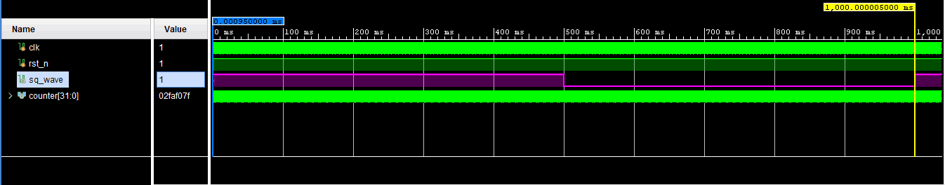
The image below shows simulation results, a Square Wave of time period 1 second i.e. 1Hz Square Wave.
Working Vivado project for this article on the Mimas A7 FPGA platform is available for download here.