
Part I
Part II
Part III
Part IV
Introduction
Though a low cost FPGA board, Saturn Spartan 6 FPGA Module is perfectly capable of running Linux with Xilinx’s popular Microblaze 32 bit soft processor. Recently we spent some time trying to figure out how to build Linux for Saturn. Surprisingly (or not!) it turned out to be fairly easy to do. Building the Linux Kernel was very easy, but creating a bootloader to boot Linux off of the on board SPI flash was a little more involved. We are excited to share what we learned with our readers. Though this article series is mainly focused on building Linux for Saturn a Xilinx Spartan 6 based FPGA module with DDR Memory, the general workflow is applicable to any Xilinx Microblaze based embedded system.
In this article series, we will cover the following topics. Each of these topics will be a separate article.
- Building Microblaze based embedded platform for Linux using Xilinx EDK
- Creating Device Tree and building Linux
- Booting Linux using XMD
- Creating a bootloader to load Linux kernel from SPI flash
You can read more about Saturn at the product page. User manual and tools can be downloaded from the same page.

Saturn Spartan 6 FPGA Module with IO Breakout board
Tool Version Compatibility and Help
This article series uses Xilinx EDK shipped with Xilinx ISE 14.6. So the screenshots and directions/commands may be different on your system if you are using a different version. Please adapt the steps mentioned in this article to make it work with your specific tool version. The best place to ask questions about ISE, EDK (XPS/SDK), Microblaze and Spartan 6 FPGA is Xilinx community forums at http://forums.xilinx.com/. You may optionally open a web case at http://www.xilinx.com/support/clearexpress/websupport.htm. Questions specific to Saturn Spartan 6 FPGA Development Board may be asked at the comments section on the product page or contact Numato Lab. Please note that author uses Windows to run Xilinx tools and Ubuntu 14.04 or compatible for building Linux kernel.
This article series was written in June 2014. Over time, the tools and Linux kernel itself will evolve and some of the specific steps included in this article series may become incorrect/invalid. If you come across such a situation, please let us know and we will try to fix it. If you have a fix, please share with fellow readers in the comments section below. It is recommended that you have the following tools/software available to follow this tutorial successfully.
- Saturn Spartan 6 FPGA Module with DDR
- Saturn configuration tool (Download from product page)
- Xilinx ISE installed with Xilinx EDK (Download from www.xilinx.com. This tutorial uses ISE 14.6)
- Buildroot (This tutorial uses 2014.5 release. You can download the latest release from here)
- Xilinx Platform Cable – USB (Optional but very useful for debugging)
All files that is used/generated while writing this article series can be downloaded here.
Building Microblaze based embedded platform for Linux using Xilinx EDK
Since Saturn being a FPGA platform which is not a microprocessor rather a collection configurable logic elements, we need to create a microprocessor out of the logic elements/resources available. Doing this from the scratch is going to be very difficult. Fortunately Xilinx already did this for us and the processor design is called Microblaze. All that we need to do is to use Microblaze in our design and make appropriate connections.
Before continuing to build the Microblaze embedded platform for Linux, it may be worth reading this article to get familiar with Xilinx EDK and Saturn.
Now let’s get started. We will need to use XPS base System Builder (BSB) to create a new project. To make the process easier, download BSB Wizard files from here and extract to the folder “C:\Xilinx\xx.xx\ISE_DS\EDK\board”. Once extracted, the complete path to the file should look like “C:\Xilinx\xx.xx\ISE_DS\EDK\board\NumatoLab\ipxact\Saturn_LX45_V3\data”. Now go to All Programs > Xilinx Design Tools > EDK and start Xilinx Platform Studio. Once XPS is loaded, click on “New BSB Project” under File menu or press Ctrl + Shift + B to invoke the BSB wizard. If everything went fine, you should be presented with BSB wizard window as shown below.
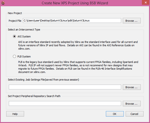
Enter path to a folder where you want to store the project and a project name (Here the project name is SaturnV3Linux in the image above). Select AXI System in the interconnect Type section and click OK. In the next page of the wizard, select “Numato Lab” from the board Vendor combo box (This option should be available if you have placed the BSB wizard support files for Saturn properly as mentioned earlier). Select Saturn LX45 and 3.0 from Board Name and Board version combo boxes respectively and click “Next” button to go to the next page.

Leave the Optimization Strategy to its default value and click next.

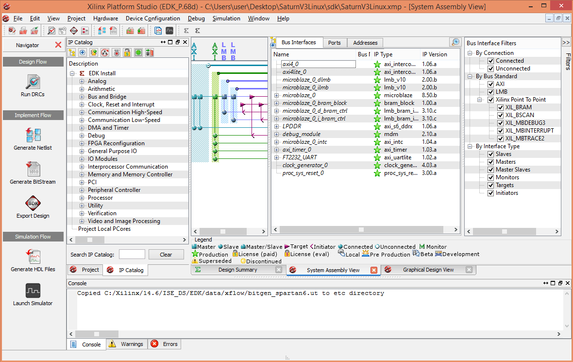
By default, FT2232 UART, LPDDR and GPIO peripherals will be selected. Select and remove all GPIO peripherals since we won’t use them in this project. Select FT2232_UART peripheral and set the baud rate to 115200 and check the “Use Interrupt” check box. Then select “axi_timer” in the “Available Peripherals” list and add that to the system. Select the timer and check the “Use Interrupt” check box. Make sure everything is setup as shown in the image above and click “Finish” button. Now Xilinx Platform Studio will generate a project for you based on the selections you made in the BSB wizard. If everything went well, you will be presented with a window as shown below.
Now we will need to add one more peripheral IP to complete our system design. From the IP catalog on the left, drag and drop the AXI SPI Interface (under “Communication Low-Speed” category) to the “System Assembly View” and connect the IP to microblaze_0 when asked.
Now we will configure the peripheral IPs. Right click on microblaze_0 in the “System Assembly View > Bus Interfaces” tab and select “Configure IP” from the pop up menu. The Microblaze Configuration Wizard will pop up. Select “Linux with MMU” under the “Select Configuration” options (Please see image below).

Click OK to accept the new settings. You can click on the “Advanced” button to tweak Microblaze IP settings further (optional).
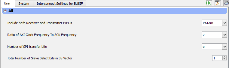
Next right click on axi_spi_0 peripheral and select “Configure IP” from the popup menu. Disable Input/Output FIFO and set the clock frequency ratio to 2. Leave all other settings to defaults and click OK. Please see the image below for reference.
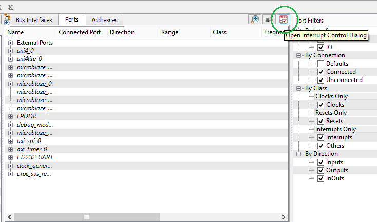
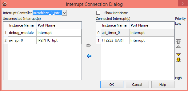
At this point, we have finished configuring Microblaze CPU and all peripherals. The next step is to route all peripheral interrupts to the microblaze CPU through the interrupt controller. To configure interrupts, go to the “Ports” tab in “System Assembly View” and locate the “Open interrupt Control Dialog” button. This button is a little tricky to locate. Please see the image below for help.
In the interrupt control dialog box, make sure that both FT2232_UART and axi_timer_0 are connected to the interrupt controller and debug_module and axi_spi_0 are not connected to the interrupt controller as shown in the image below.
Now we need to add a few lines to the user Constraints File to map FPGA IOs for accessing SPI Flash. Click on the “project” tab next to “IP Catalog” tab and double click on the UCF file “SaturnV3Linux.ucf” to open it. Add the following lines to the end of the UCF file and save.
NET axi_spi_0_SCK_pin LOC = "R15"   |  IOSTANDARD = "LVCMOS33";
NET axi_spi_0_SS_pin LOC = "V3"     |  IOSTANDARD = "LVCMOS33";
NET axi_spi_0_MOSI_pin LOC = "T13"  |  IOSTANDARD = "LVCMOS33";
NET axi_spi_0_MISO_pin LOC = "R13"  |  IOSTANDARD = "LVCMOS33";
Go back to the “System Assembly View” and select “Addresses” tab and make sure all peripherals has a base address assigned (XPS will take care of this automatically, but just in case). Note the base address of LPDDR memory, we will need it when building Linux kernel. At this point, we are ready to build the project. Click on the “generate bitstream” button the left side pane to start build process. If build fails due to timing closure issues, go to project menu in XPS, select Project Options and uncheck “Treat timing failures as errors”. This should help the build complete without errors.