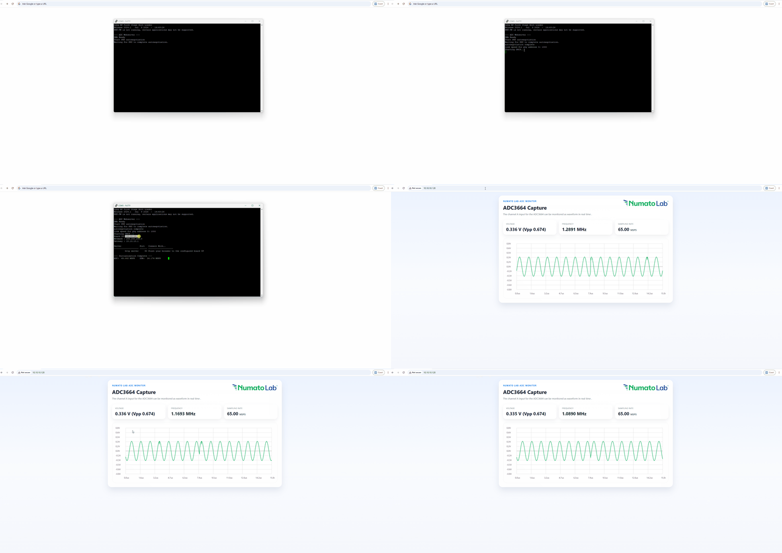
In this project, we connect the Texas Instruments ADC3664 EVM to the EagleCore ZU-Plus MPSoC and turn the FPGA into a real-time high-speed data acquisition system. The ADC samples an analog signal at 65 MSPS, sends the digitized data to the FPGA through serial LVDS, and the FPGA captures, reconstructs, and transfers those samples into DDR memory using AXI DMA.
But we don’t stop at capturing numbers.
The Vitis application brings the data out through Ethernet using lwIP and serves a lightweight web interface where the captured ADC waveform can be viewed directly from a browser. The FPGA also includes a dedicated sample counter to measure the actual ADC data rate and verify that the LVDS receiver is handling the expected ~65 MSPS data stream.
From applying a signal from a function generator to watching its waveform appear in a browser, this project covers the complete path:
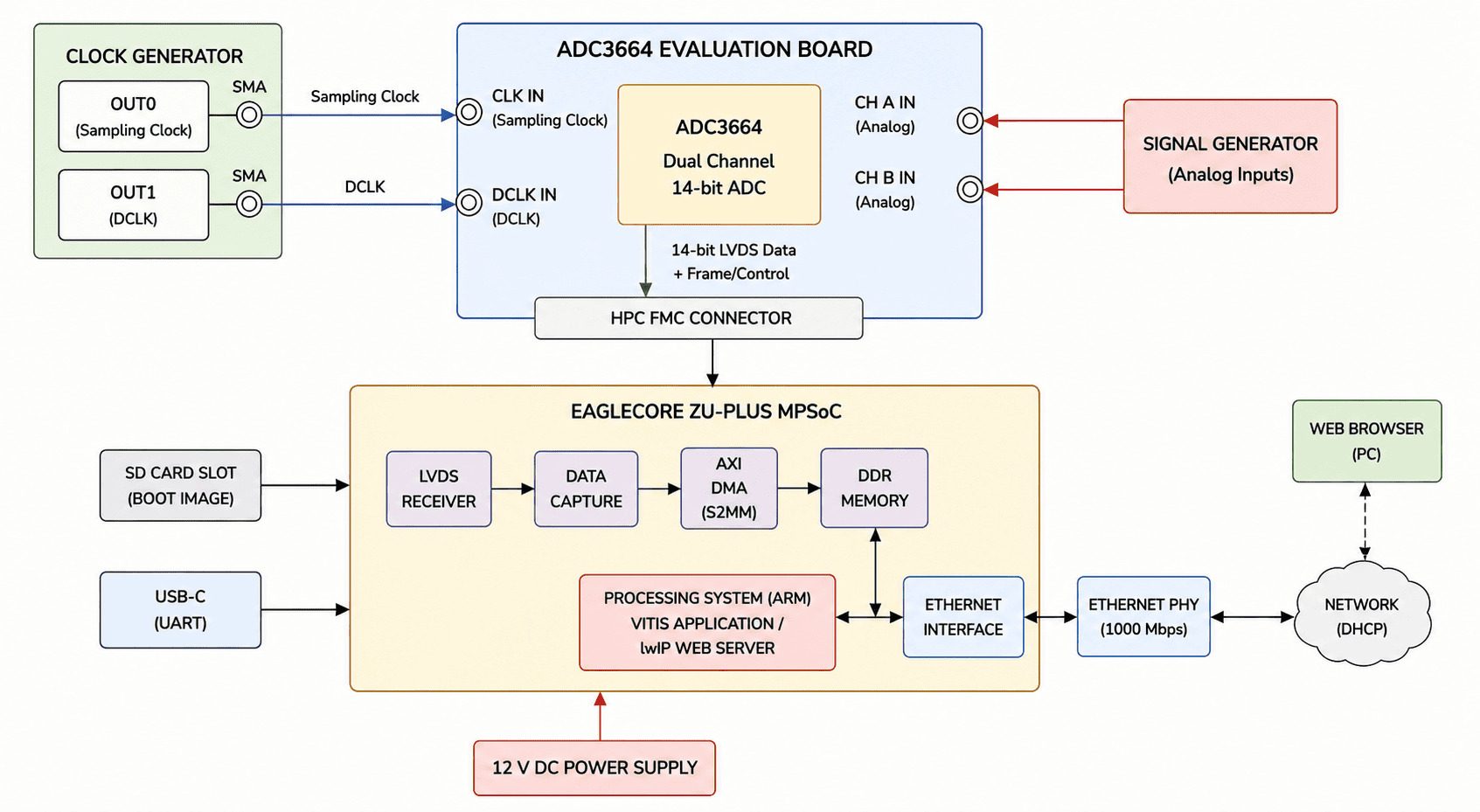
Analog Signal → ADC3664 EVM → Serial LVDS → EagleCore ZU-Plus MPSoC → AXI DMA → DDR → Vitis → Ethernet → Web Browser
Let’s get into how the ADC3664 and EagleCore ZU-Plus MPSoC work together to turn a high-speed analog signal into a live digital waveform.
What This Demo Shows
This project highlights how the EagleCore ZU-Plus MPSoC can be used as a high-speed FPGA-based data acquisition platform. In this demo, the board:
- Interfaces with the Texas Instruments ADC3664 EVM for high-speed analog-to-digital conversion
- Captures 65 MSPS serial LVDS ADC data using the FPGA programmable logic
- Reconstructs the ADC samples and transfers them through an AXI-Stream data path
- Uses AXI DMA to transfer captured ADC data into DDR memory
- Uses a dedicated FPGA counter to measure the actual ADC sample throughput
- Runs a Vitis application on the MPSoC processing system
- Uses lwIP and Ethernet to serve the captured data to a PC
- Provides a web-based waveform viewer for real-time visualization of the ADC signal
The result?
A complete high-speed ADC acquisition system running on the EagleCore ZU-Plus MPSoC, taking an analog signal at the ADC input, capturing it through the FPGA’s LVDS interface, storing the samples in DDR, and displaying the resulting waveform directly in a web browser.
Hardware Setup
The following connections are required:
- Make sure the EagleCore ZU-Plus MPSoC is configured for SD card boot mode.
- Insert the SD card containing the required boot image(downlaod the BOOT.BIN form here) into the SD card slot of the EagleCore carrier board.
- Connect the ADC3664 EVM HPC FMC connector to the HPC FMC connector of the EagleCore ZU-Plus MPSoC.
- Connect the Channel A SMA input of the ADC3664 EVM to the function generator for supplying the analog test signal.
- Connect the both Sampling clock input and DCLK input SMA cable to the clock generator
- Connect a 12 V DC power supply to the EagleCore board.
- Connect a USB-C cable to the EagleCore board for UART communication and debugging.
- Connect an Ethernet cable from the EagleCore board to the main network connection. The board uses DHCP to obtain its IP address automatically.
- Configure Clock generator for the ADC sampling clock and the ADC DCLK before starting the acquisition.
Running the Project
After making all the required connections and verifying the clock and signal connections:
- Power on the EagleCore ZU-Plus MPSoC with the board set to SD card boot mode.
- The board will boot the project from the SD card.
- Open PuTTY and select the COM port connected to the EagleCore board.
- Set the baud rate to 115200.
- The UART terminal will display the project status, including the DHCP-assigned IP address, ADC sampling rate, DDR throughput, and webserver status.
- Once the IP address is displayed and the webserver is running, the system is ready to access the ADC waveform through Ethernet.
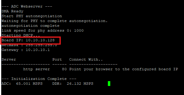
Once the board’s IP address is displayed in PuTTY, open a web browser on the same network and enter the displayed IP address in the address bar.
The ADC3664 Capture web console will open and provide a real-time view of the acquired Channel A signal.
The web console displays:
- Voltage – displays the current signal voltage and measured Vpp.
- Frequency – displays the measured frequency of the input signal.
- Sampling Rate – displays the measured ADC sampling rate in MSPS.
- Waveform – displays the captured Channel A waveform in real time.