Introduction
The EagleCore C03 carrier features three Q-pair differential mezzanine connectors, enabling compatibility with a range of AMD System-on-Module (SoM) solutions, including the EagleCore ZU-Plus MPSoC SoM. It also introduces FPIC (Flexible Peripheral Interface Connector), an I/O expansion interface developed by Numato Lab to provide flexible and scalable peripheral connectivity. The board includes three FPIC interfaces, where one supports GT-based high-speed connections for high-bandwidth expansion, while the other two FPIC ST connectors are intended for general-purpose peripheral interfacing.
The carrier board offers a rich set of onboard features designed for flexibility and ease of use. These include an SD card slot for data and program storage, and a MIPI CSI-2 camera interface for high-speed image and video capture. Additional peripherals include a fan header for thermal management, two PMOD connectors, HDMI transmitter output, USB Host support, two CAN headers, SMA connectors, four user push buttons, and four user LEDs. The board also provides a USB Type-C interface for UART communication and USB-based programming, a dedicated JTAG header for debugging and development, and I/O voltage selection header for the FPIC connectors.
Board Features
- Three Q-pair differential mezzanine connectors for high-speed SoM interfacing
- FTDI FT2232H for FPGA and Host communication
- RJ45 JACK
- USB Type-C connector for UART communication and programming
- USB connector with host functionality
- HDMI output connector
- 12V DC power supply
- AMD-compatible JTAG Header for programming and debugging.
- Dual FPIC ST connector for flexible peripheral connectivity.
- Single FPIC GT connector for high-speed expansion
- 2 x CAN header
- User-defined LEDs and switches
- MIPI connector for video and image processing
- 3 x SMA connectors
- I/O voltage selection header for FPIC connectors
- 12V fan header for thermal management
How to use EagleCore C03
The following sections describe how to use this Carrier module in detail.
Hardware Accessories Required
In addition to the module, you may require the accessories listed below for a convenient and expedited installation:
- 12 V DC Power Supply
- USB Type-C cable (for serial communication and programming).
- AMD Platform Cable USB II compatible JTAG programmer (Optional).
- EagleCore SoM module.
Connection Diagram
Note: The RTC Coin cell battery are kept below the carrier.
DC Power Supply
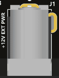
The EagleCore C03 is configured to use power from the DC power supply by connecting it to the External DC Jack (J1). The external power supply should be in the range of +12V 5A.
Power Switch
The Power Switch (SW1) is used to switch on/off the board. Sliding it to ON to supply power from the External DC Jack to the board. Sliding it to OFF to power off the board.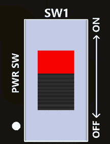
Power LED
The EagleCore C03 has a power LED (PWR) that will illuminate when the board receives sufficient power during startup.
Reset
The EagleCore C03 has a push button switch (DEV RST) for resetting the entire system. This pin is connected to the system reset pin of the FPGA.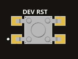
PROGB
The EagleCore C03 includes a dedicated switch (PROG B) for PROGB functionality, which is connected to the corresponding PROGB pin on the FPGA.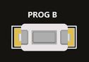
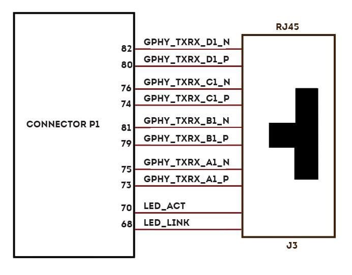
Gigabit Ethernet Port
The EagleCore C03 supports 1 Gigabit ethernet communication lanes (J3) which support 10/100/1000Mbps Ethernet interface. It also has an additional Activity and Link LED for providing visual indication for the user about the status of the ethernet. The Ethernet LINK LED indicates the presence of a network connection when illuminated, while the Gigabit Ethernet ACTIVITY LED signals active data transmission or reception over the network.
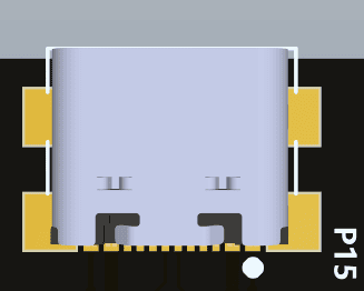
USB Interface
The onboard USB connector (P15) helps a PC/Linux/Mac computer to communicate with this module.
Use a USB type C cable to connect with a PC. This port will act as both JTAG and UART interface.
USB Host Connector
The EagleCore C03 provides a USB 2.0 Host interface (P8) through a USB Type-A connector, enabling connection to external USB devices such as Webcam, keyboards, storage drives, and other peripherals. In this configuration, the board operates exclusively in Host mode. An onboard LED (USB_5V) is connected to the VBUS line to indicate the presence of 5V power on the USB interface.
MicroSD Card
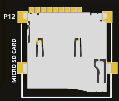 The EagleCore C03 supports a microSD card slot (P12), providing additional non-volatile storage capacity. The microSD interface operates at 3.3 V, while the carrier’s native I/O operates at 1.8 V. To ensure proper signal compatibility, an onboard level translator is used to convert the 1.8 V I/O signals to 3.3 V. This compact and removable storage solution is well suited for storing large data sets, boot images, or configuration data that can be accessed during system startup.
Mode Selection DIP Switches
EagleCore C03 has DIP switches (SW8) for changing the boot configuration of the FPGA based on the required functionality. Users can utilize all four pins or only the necessary ones, leaving the remaining MODE pins unconnected.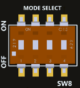
EagleCore ZU-Plus MPSoC SOM
The boot configuration of the EagleCore ZU-Plus MPSoC SoM will be based on the below configuration of switches: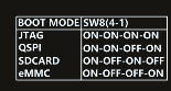
| MODE3 | MODE2 | MODE1 | MODE0 | |
|---|---|---|---|---|
| JTAG | 0 | 0 | 0 | 0 |
| QSPI (32Bit) | 0 | 0 | 1 | 0 |
| SD Card(2.0) | 0 | 1 | 0 | 1 |
| EMMC (1.8V) | 0 | 1 | 1 | 0 |
RTC Coin Cell Holder
The EagleCore C03 has a Coin Cell Holder (BT1) to support 1.8V coin cell that will support 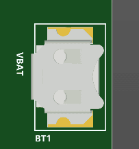
backup voltage for RTC when main power supply is off. RTC maintains accurate timekeeping through these battery-backup. The battery should be kept in the carrier board for providing voltage if the main power is off.
CAN Header
The EagleCore SOM Carrier has 2 CAN (P14)headers dedicated for CAN communication interfaces.
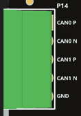
| Pin No. | Signal Name | Function |
|---|---|---|
| 1 | CANH | CAN0_P |
| 2 | CANL | CAN0_N |
| 3 | CANH | CAN1_P |
| 4 | CANL | CAN1_N |
| 5 | GND | GND |
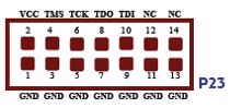
JTAG Header
EagleCore C03 supports standard JTAG Headers for programming and debugging purposes.
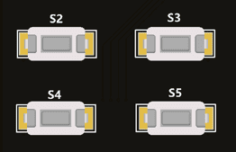
User Defined LEDs and Push Buttons
EagleCore C03 provides 4 user-defined LEDs.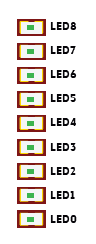
EagleCore C03 provides 4 Push buttons (S2, S3, S4, S5) for user-defined purposes.
PGM_SEL switch
The EagleCore C03 supports both JTAG and FTDI programming for AMD FPGA boards. The configuration can be changes using PGM_SEL switch. By default, switch SW4 is in the ON position for JTAG programming configuration. When switched to the OFF position, it will configure the board for FTDI programming.
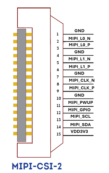
MIPI Header
The EagleCore c03 has a dedicated lines for MIPI CSI-2 connector (P24). MIPI CSI-2 is a standard interface for connecting cameras to FPGAs, enabling high-speed, efficient, and scalable image and video data transmission.
| Connector Pin Number | Signal Name | SoM connector Pin No. (Connector name) | SoM connector Pin Name |
|---|---|---|---|
| 1 | GND | ||
| 2 | MIPI_L0_N | 39 (P2) | IO8_N |
| 3 | MIPI_L0_P | 37 (P2) | IO8_P |
| 4 | GND | ||
| 5 | MIPI_L1_N | 43 (P2) | IO10_N |
| 6 | MIPI_L1_P | 41 (P2) | IO10_P |
| 7 | GND | ||
| 8 | MIPI_CLK_N | 34 (P2) | IO7_N |
| 9 | MIPI_CLK_P | 32 (P2) | IO7_P |
| 10 | GND | ||
| 11 | MIPI_PWUP | 47 (P3) | IO12_P |
| 12 | MIPI_GPIO | 49 (P3) | IO12_N |
| 13 | MIPI_SCL | 51 (P3) | IO14_P |
| 14 | MIPI_SDA | 53 (P3) | IO14_N |
| 15 | VDD3V3 |
PMOD
PMOD0 (p10)
| Connector Pin No. | Pin Name | SoM connector Pin No. (Connector name) | SoM connector Pin Name | Connector Pin No. | Pin Name | SoM connector Pin No. (Connector name) | SoM connector Pin Name |
|---|---|---|---|---|---|---|---|
| 1 | CONN0_D1 | 57 (P3) | IO16_P | 7 | CONN0_D5 | 59 (P3) | IO16_N |
| 2 | CONN0_D2 | 58 (P3) | IO17_P | 8 | CONN0_D6 | 60 (P3) | IO17_N |
| 3 | CONN0_D3 | 61 (P3) | IO18_P | 9 | CONN0_D7 | 63 (P3) | IO18_N |
| 4 | CONN0_D4 | 62 (P3) | IO19_P | 10 | CONN0_D8 | 64 (P3) | IO19_N |
| 5 | GND | 11 | GND | ||||
| 6 | VDD3V3 | 12 | VDD3V3 |
PMOD1 (p16)
| Connector Pin No. | Pin Name | SoM connector Pin No. (Connector name) | SoM connector Pin Name | Connector Pin No. | Pin Name | SoM connector Pin No. (Connector name) | SoM connector Pin Name |
|---|---|---|---|---|---|---|---|
| 1 | CONN0_D1 | 57 (P3) | IO16_P | 7 | CONN0_D5 | 59 (P3) | IO16_N |
| 2 | CONN0_D2 | 58 (P3) | IO17_P | 8 | CONN0_D6 | 60 (P3) | IO17_N |
| 3 | CONN0_D3 | 61 (P3) | IO18_P | 9 | CONN0_D7 | 63 (P3) | IO18_N |
| 4 | CONN0_D4 | 62 (P3) | IO19_P | 10 | CONN0_D8 | 64 (P3) | IO19_N |
| 5 | GND | 11 | GND | ||||
| 6 | VDD3V3 | 12 | VDD3V3 |
XADC (On-chip analog-to-digital converter)
The EagleCore c03 have dedicated header (P17) for differential analog input.

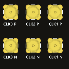
SMA Connectors
The EagleCore c03 supports 3 SMA connectors for differential transceiver clocks. Users can
utilize this connector to meet additional transceiver clock requirements.
| Connector Pin No. (P1) | Connector Pin Name | Signal Name |
|---|---|---|
| 8 | CLK1_P | CLK_01_P |
| 10 | CLK1_N | CLK_01_N |
| 37 | CLK2_P | CLK_02_P |
| 39 | CLK2_N | CLK_02_N |
| 38 | CLK3_P | CLK_03_P |
| 40 | CLK3_N | CLK_03_N |
SOM Connector Header
Connector P1
| Pin No. | Signal Name | Pin Name | Pin No. | Signal Name | Pin Name |
|---|---|---|---|---|---|
| 1 | VDD1V8 | M_AUX1V8 | 2 | VCC3V3 | M_AUX3V3 |
| 3 | VDD1V8 | M_AUX1V8 | 4 | VCC3V3 | M_AUX3V3 |
| 5 | GND | GND | 6 | GND | GND |
| 7 | CLK0_P | FPICC_CLK0_P | 8 | CLK1_P | SMA_CLK1_P |
| 9 | CLK0_N | FPICC_CLK0_N | 10 | CLK1_N | SMA_CLK1_N |
| 11 | GND | GND | 12 | GND | GND |
| 13 | RX0_P | FPICC_RX0_P | 14 | TX0_P | FPICC_TX0_P |
| 15 | RX0_N | FPICC_RX0_N | 16 | TX0_N | FPICC_TX0_N |
| 17 | GND | GND | 18 | GND | GND |
| 19 | RX1_P | FPICC_RX1_P | 20 | TX1_P | FPICC_TX1_P |
| 21 | RX1_N | FPICC_RX1_N | 22 | TX1_N | FPICC_TX1_N |
| 23 | GND | GND | 24 | GND | GND |
| 25 | RX2_P | FPICC_RX2_P | 26 | TX2_P | FPICC_TX2_P |
| 27 | RX2_N | FPICC_RX2_N | 28 | TX2_N | FPICC_TX2_N |
| 29 | GND | GND | 30 | GND | GND |
| 31 | RX3_P | FPICC_RX3_P | 32 | TX3_P | FPICC_TX3_P |
| 33 | RX3_N | FPICC_RX3_N | 34 | RX3_N | FPICC_TX3_N |
| 35 | GND | GND | 36 | GND | GND |
| 37 | CLK2_P | SMA_CL2_P | 38 | CLK3_P | SMA_CLK3_P |
| 39 | CLK2_N | SMA_CL2_N | 40 | CLK3_N | SMA_CLK3_N |
| 41 | GND | GND | 42 | GND | GND |
| 43 | RX4_P | FPICC_RX4_P | 44 | TX4_P | FPICC_TX4_P |
| 45 | RX4_N | FPICC_RX4_N | 46 | TX4_N | FPICC_TX4_N |
| 47 | GND | GND | 48 | GND | GND |
| 49 | RX5_P | FPICC_RX5_P | 50 | TX5_P | FPICC_TX5_P |
| 51 | RX5_N | FPICC_RX5_N | 52 | TX5_N | FPICC_TX5_N |
| 53 | GND | GND | 54 | GND | GND |
| 55 | RX6_P | FPICC_RX6_P | 56 | TX6_P | FPICC_TX6_P |
| 57 | RX6_N | FPICC_RX6_N | 58 | TX6_N | FPICC_TX6_N |
| 59 | GND | GND | 60 | GND | GND |
| 61 | RX7_P | FPICC_RX7_P | 62 | TX7_P | FPICC_TX7_P |
| 63 | RX7_N | FPICC_RX7_N | 64 | TX7_N | FPICC_TX7_N |
| 65 | GND | GND | 66 | GND | GND |
| 67 | CLK4_P | FPICC_CLK1_P | 68 | LED/LINK | LED1/Link |
| 69 | CLK4_N | FPICC_CLK1_N | 70 | LED/ACT | LED1/Activity |
| 71 | GND | GND | 72 | GND | GND |
| 73 | GPHY_A1_P | GPHY_TXRX_A1_P | 74 | GPHY_C1_P | GPHY_TXRX_C1_P |
| 75 | GPHY_A1_N | GPHY_TXRX_A1_N | 76 | GPHY_C1_N | GPHY_TXRX_C1_N |
| 77 | GND | GND | 78 | GND | GND |
| 79 | GPHY_B1_P | GPHY_TXRX_B1_P | 80 | GPHY_D1_P | GPHY_TXRX_D1_P |
| 81 | GPHY_B1_N | GPHY_TXRX_B1_N | 82 | GPHY_D1_N | GPHY_TXRX_D1_N |
| 83 | GND | GND | 84 | GND | GND |
| 85 | CAN0_TX | CAN0 _TX | 86 | CAN1_TX | CAN1_TX |
| 87 | CAN0_RX | CAN0_RX | 88 | CAN1_RX | CAN1_RX |
| 89 | GND | GND | 90 | GND | GND |
| 91 | PS_ERROR_STATUS | PS_ERROR_STATUS | 92 | V_P | V_P |
| 93 | PS_ERROR_OUT | PS_ERROR_OUT | 94 | V_N | V_N |
| 95 | VBAT | VBAT | 96 | PROG_B | PROG_B |
| 97 | MIO | FAN_MIO | 98 | IO | PG_M2C3 |
| 99 | GND | GND | 100 | GND | GND |
| 101 | IO0_P | FPICC_IO0_P | 102 | IO1_P | FPICB_IO24_P |
| 103 | IO0_N | FPICC_IO0_N | 104 | IO1_N | FPICB_IO24_N |
| 105 | IO2_P | FPICC_IO1_P | 106 | IO3_P | FPICB_IO25_P |
| 107 | IO2_N | FPICC_IO1_N | 108 | IO3_N | FPICB_IO25_N |
| 109 | GND | GND | 110 | GND | GND |
| 111 | IO4_P | SW0 | 112 | IO5_P | LED_0 |
| 113 | IO4_N | SW1 | 114 | IO5_N | LED_1 |
| 115 | IO6_P | SW2 | 116 | IO7_P | LED_2 |
| 117 | IO6_N | SW3 | 118 | IO7_N | LED_3 |
| 119 | GND | GND | 120 | GND | GND |
| G8 | GND | GND | G1 | GND | GND |
| G7 | GND | GND | G2 | GND | GND |
| G6 | GND | GND | G3 | GND | GND |
| G5 | GND | GND | G4 | GND | GND |
Connector P2
| Pin No. | Signal Name | Pin Name | Pin No. | Signal Name | Pin Name |
|---|---|---|---|---|---|
| 1 | VIN | 5P0 | 2 | VIN | 5P0 |
| 3 | VIN | 5P0 | 4 | VIN | 5P0 |
| 5 | VIN | 5P0 | 6 | VIN | 5P0 |
| 7 | GND | GND | 8 | GND | GND |
| 9 | GND | GND | 10 | GND | GND |
| 11 | VCC_IO | VIO1 | 12 | VCC_IO | M_AUX1V8 |
| 13 | VCC_IO | VIO1 | 14 | VCC_IO | M_AUX1V8 |
| 15 | GND | GND | 16 | GND | GND |
| 17 | IO0_P | FPICB_IO12_CC_P | 18 | IO1_P | FPICB_IO13_CC_P |
| 19 | IO0_N | FPICB_IO12_CC_N | 20 | IO1_N | FPICB_IO13_CC_N |
| 21 | IO2_P | FPICB_IO14_P | 22 | IO3_P | FPICB_IO15_P |
| 23 | IO2_N | FPICB_IO14_N | 24 | IO3_N | FPICB_IO15_N |
| 25 | GND | GND | 26 | GND | GND |
| 27 | IO4_P | FPICB_IO16_P | 28 | IO5_P | FPICB_IO17_CC_P |
| 29 | IO4_N | FPICB_IO16_N | 30 | IO5_N | FPICB_IO17_CC_N |
| 31 | IO6_P | FPICB_IO18_CC_P | 32 | IO7_P | MIPI_CLK_P |
| 33 | IO6_N | FPICB_IO18_CC_N | 34 | IO7_N | MIPI_CLK_N |
| 35 | GND | GND | 36 | GND | GND |
| 37 | IO8_P | MIPI_L0_P | 38 | IO9_P | FPICB_IO19_P |
| 39 | IO8_N | MIPI_L0_N | 40 | IO9_N | FPICB_IO19_N |
| 41 | IO10_P | MIPI_L1_P | 42 | IO11_P | FPICB_IO21_CC_P |
| 43 | IO10_N | MIPI_L1_N | 44 | IO11_N | FPICB_IO21_CC_N |
| 45 | GND | GND | 46 | GND | GND |
| 47 | IO12_P | FPICB_IO20_P | 48 | IO13_P | FPICB_IO23_P |
| 49 | IO12_N | FPICB_IO20_N | 50 | IO13_N | FPICB_IO23_N |
| 51 | IO14_P | FPICB_IO22_P | 52 | IO15_P | FPICB_IO3_CC_P |
| 53 | IO14_N | FPICB_IO22_N | 54 | IO15_N | FPICB_IO3_CC_N |
| 55 | GND | GND | 56 | GND | GND |
| 57 | IO16_P | FPICB_IO2_P | 58 | IO17_P | FPICB_IO5_CC_P |
| 59 | IO16_N | FPICB_IO2_N | 60 | IO17_N | FPICB_IO5_CC_N |
| 61 | IO18_P | FPICB_IO4_CC_P | 62 | IO19__P | HDMI_TX_CLK_P |
| 63 | IO18_N | FPICB_IO4_CC_N | 64 | IO19_N | HDMI_TX_CLK_N |
| 65 | GND | GND | 66 | GND | GND |
| 67 | IO20_P | HDMI_TX0_P | 68 | IO21_P | HDMI_TX2_P |
| 69 | IO20_N | HDMI_TX0_N | 70 | IO21_N | HDMI_TX2_N |
| 71 | IO22_P | HDMI_TX1_P | 72 | IO23_P | FPICA_IO1_CC_P |
| 73 | IO22_N | HDMI_TX1_N | 74 | IO23_N | FPICA_IO1_CC_N |
| 75 | GND | GND | 76 | GND | GND |
| 77 | IO24_P | FPICA_IO0_CC_P | 78 | IO25_P | FPICA_I03_P |
| 79 | IO24_N | FPICA_IO0_CC_N | 80 | IO25_N | FPICA_I03_N |
| 81 | IO26_P | FPICA_IO2_P | 82 | IO27_P | FPICA_IO15_CC_P |
| 83 | IO26_N | FPICA_IO2_N | 84 | IO27_N | FPICA_IO15_CC_N |
| 85 | GND | GND | 86 | GND | GND |
| 87 | IO28_P | FPICA_IO4_P | 88 | IO29_P | FPICA_I07_P |
| 89 | IO28_N | FPICA_IO4_N | 90 | IO29_N | FPICA_I07_N |
| 91 | IO30_P | FPICA_IO6_CC_P | 92 | IO31_P | FPICA_IO9_CC_P |
| 93 | IO30_N | FPICA_IO6_CC_P | 94 | IO31_N | FPICA_IO9_CC_N |
| 95 | GND | GND | 96 | GND | GND |
| 97 | IO32_P | FPICA_IO8_P | 98 | IO33_P | FPICA_IO12_CC_P |
| 99 | IO32_N | FPICA_IO8_N | 100 | IO33_N | FPICA_IO12_CC_N |
| 101 | IO34_P | FPICA_IO10_P | 102 | IO35_P | FPICA_IO13_CC_P |
| 103 | IO34_N | FPICA_IO10_N | 104 | IO35_N | FPICA_IO13_CC_N |
| 105 | GND | GND | 106 | GND | GND |
| 107 | IO36_P | FPICA_IO11_P | 108 | IO37_P | FPICA_I014_P |
| 109 | IO36_N | FPICA_IO11_N | 110 | IO37_N | FPICA_I014_N |
| 111 | SD_CLK | SD_SCK | 112 | SD_DATA0 | SD_DATA0 |
| 113 | SD_CMD | SD_CMD | 114 | SD_DATA1 | SD_DATA1 |
| 115 | UART_RXD | UART_RX | 116 | SD_DATA2 | SD_DATA2 |
| 117 | UART_RXD | UART_TX | 118 | SD_DATA3 | SD_DATA3 |
| 119 | GND | GND | 120 | GND | GND |
| G8 | GND | GND | G1 | GND | GND |
| G7 | GND | GND | G2 | GND | GND |
| G6 | GND | GND | G3 | GND | GND |
| G5 | GND | GND | G4 | GND | GND |
Connector P3
| Pin No. | Signal Name | Pin Name | Pin No. | Signal Name | Pin Name |
|---|---|---|---|---|---|
| 1 | VIN | 5P0 | 2 | VIN | 5P0 |
| 3 | VIN | 5P0 | 4 | VIN | 5P0 |
| 5 | VIN | 5P0 | 6 | VIN | 5P0 |
| 7 | GND | GND | 8 | GND | GND |
| 9 | GND | GND | 10 | GND | GND |
| 11 | VCC3V3 | M_AUX3V3 | 12 | VCC_IO | VIO2 |
| 13 | VCC3V3 | M_AUX3V3 | 14 | VCC_IO | VIO2 |
| 15 | GND | GND | 16 | GND | GND |
| 17 | IO0_P | FPICB_IO0_CC_P | 18 | IO1_P | FPICB_IO1_CC_P |
| 19 | IO0_N | FPICB_IO0_CC_N | 20 | IO1_N | FPICB_IO1_CC_N |
| 21 | IO2_P | FPICB_IO2_P | 22 | IO3_P | FPICB_IO3_P |
| 23 | IO2_N | FPICB_IO2_N | 24 | IO3_N | FPICB_IO3_N |
| 25 | GND | GND | 26 | GND | GND |
| 27 | IO4_P | FPICB_IO4_P | 28 | IO5_P | FPICB_IO5_P |
| 29 | IO4_N | FPICB_IO4_N | 30 | IO5_N | FPICB_IO5_N |
| 31 | IO6_P | FPICB_IO8_CC_P | 32 | IO7_P | FPICB_IO7_P |
| 33 | IO6_N | FPICB_IO8_CC_N | 34 | IO7_N | FPICB_IO7_N |
| 35 | GND | GND | 36 | GND | GND |
| 37 | IO8_P | FPICB_IO6_P | 38 | IO9_P | FPICB_IO9_CC_P |
| 39 | IO8_N | FPICB_IO6_N | 40 | IO9_N | FPICB_IO9_CC_N |
| 41 | IO10_P | FPICB_IO10_P | 42 | IO11_P | FPICB_IO11_P |
| 43 | IO10_N | FPICB_IO10_N | 44 | IO11_N | FPICB_IO11_P |
| 45 | GND | GND | 46 | GND | GND |
| 47 | IO12_P | MIPI_PWUP | 48 | IO13_P | HDMI_TX_CEC |
| 49 | IO12_N | MIPI_GPIO | 50 | IO13_N | HDMI_TX_HOT |
| 51 | IO14_P | MIPI_SCL | 52 | IO15_P | HDMI_TX_SCL |
| 53 | IO14_N | MIPI_SDA | 54 | IO15_N | HDMI_TX_SDA |
| 55 | GND | GND | 56 | GND | GND |
| 57 | IO16_P | CONN0_D1 | 58 | IO17_P | CONN0_D2 |
| 59 | IO16_N | CONN0_D5 | 60 | IO17_N | CONN0_D6 |
| 61 | IO18_P | CONN0_D3 | 62 | IO19_P | CONN0_D4 |
| 63 | IO18_N | CONN0_D7 | 64 | IO19_N | CONN0_D8 |
| 65 | GND | GND | 66 | GND | GND |
| 67 | IO20_P | CONN1_D1 | 68 | IO21_P | CONN1_D2 |
| 69 | IO20_N | CONN1_D5 | 70 | IO21_N | CONN1_D6 |
| 71 | IO22_P | CONN1_D3 | 72 | IO23_P | CONN1_D4 |
| 73 | IO22_N | CONN1_D7 | 74 | IO23_N | CONN1_D8 |
| 75 | GND | GND | 76 | GND | GND |
| 77 | IO24_P | SCL_FPIC | 78 | IO25_P | PG_M2C1 |
| 79 | IO24_N | SDA_FPIC | 80 | IO25_N | PG_M2C2 |
| 81 | IO26_P | FPICA_IO16_P | 82 | IO27_P | FPICA_IO15_P |
| 83 | IO26_N | FPICA_IO16_N | 84 | IO27_N | FPICA_IO15_N |
| 85 | GND | GND | 86 | GND | GND |
| 87 | IO28_P | FPICA_IO18_CC_P | 88 | IO29_P | FPICA_IO17_CC_P |
| 89 | IO28_N | FPICA_IO18_CC_N | 90 | IO29_N | FPICA_IO17_CC_N |
| 91 | IO30_P | FPICA_IO20_CC_P | 92 | IO31_P | FPICA_IO19_P |
| 93 | IO30_N | FPICA_IO20_CC_N | 94 | IO31_N | FPICA_IO19_N |
| 95 | GND | GND | 96 | GND | GND |
| 97 | IO32_P | FPICA_IO22_P | 98 | IO33_P | FPICA_IO21_CC_P |
| 99 | IO32_N | FPICA_IO22_N | 100 | IO33_N | FPICA_IO21_CC_N |
| 101 | GND | GND | 102 | GND | GND |
| 103 | MODE 0 | MODE 0 | 104 | MODE 2 | MODE 2 |
| 105 | MODE 1 | MODE 1 | 106 | MODE 3 | MODE 3 |
| 107 | USB_DN | OTG_D_N | 108 | USB_ID | |
| 109 | USB_DP | OTG_D_P | 110 | USB_5V | OTG_USB_5V |
| 111 | JTAG_TDI | FPGA_TDI | 112 | JTAG_TDO | FPGA_TDO |
| 113 | JTAG_TMS | FPGA_TMS | 114 | JTAG_TCK | FPGA_TCK |
| 115 | IO_RESET | IO_RESET | 116 | DEV_RST | DEV_RST |
| 117 | PG_M2C | PG_GOOD | 118 | PG_C2M | PG_C2M |
| 119 | GND | GND | 120 | GND | GND |
| GND | GND | GND | GND | ||
| GND | GND | GND | GND | ||
| GND | GND | GND | GND | ||
| GND | GND | GND | GND |
FPIC – FPGA Peripheral Interface Connector
FPIC A ST
| Pin No. On The Header | Pin Name | Signal name | SoM connector Pin No. (Connector name) | SoM connector Pin Name | Pin No. On The Header | Pin Name | Signal name | SoM connector Pin No. (Connector name) | SoM connector Pin Name |
|---|---|---|---|---|---|---|---|---|---|
| 1 | 5V | 5P0 | 2 | PG_M2C | PG_M2C1 | 78 (P3) | IO25_P | ||
| 3 | GND | GND | 4 | GND | GND | ||||
| 5 | IO1_P/CLK1_P | FPICA_IO1_CC_P | 72 (P2) | IO23_P | 6 | IO0_P/CLK0_P | FPICA_IO0_CC_P | 77 (P2) | IO24_P |
| 7 | IO1_N/CLK1_N | FPICA_IO1_CC_N | 74 (P2) | IO23_N | 8 | IO0_N/CLK0_N | FPICA_IO0_CC_N | 79 (P2) | IO24_N |
| 9 | IO3_P | FPICA_IO3_P | 78 (P2) | IO25_P | 10 | IO2_P | FPICA_IO2_P | 81 (P2) | IO26_P |
| 11 | IO3_N | FPICA_IO3_N | 80 (P2) | IO25_N | 12 | IO2_N | FPICA_IO2_N | 83 (P2) | IO26_N |
| 13 | GND | GND | 14 | GND | GND | ||||
| 15 | IO5_P | FPICA_IO5_CC_P | 82 (P2) | IO27_P | 16 | IO4_P | FPICA_IO4_P | 87 (P2) | IO28_P |
| 17 | IO5_N | FPICA_IO5_CC_N | 84 (P2) | IO27_N | 18 | IO4_N | FPICA_IO4_N | 89 (P2) | IO28_N |
| 19 | IO7_P | FPICA_IO7_P | 88 (P2) | IO29_P | 20 | IO6_P | FPICA_IO6_CC_P | 91 (P2) | IO30_P |
| 21 | IO7_N | FPICA_IO7_N | 90 (P2) | IO29_N | 22 | IO6_N | FPICA_IO6_CC_N | 93 (P2) | IO30_N |
| 23 | GND | GND | 24 | GND | GND | ||||
| 25 | IO9_P/CLK3_P | FPICA_IO9_CC_P | 92 (P2) | IO31_P | 26 | IO8_P/CLK2_P | FPICA_IO8_P | 97 (P2) | IO32_P |
| 27 | IO9_N/CLK3_N | FPICA_IO9_CC_N | 94 (P2) | IO31_N | 28 | IO8_N/CLK2_N | FPICA_IO8_N | 99 (P2) | IO32_N |
| 29 | IO11_P | FPICA_IO11_P | 107 (P2) | IO36_P | 30 | IO10_P | FPICA_IO10_P | 101 (P2) | IO34_P |
| 31 | IO11_N | FPICA_IO11_N | 109 (P2) | IO36_N | 32 | IO10_N | FPICA_IO10_N | 103 (P2) | IO34_N |
| 33 | GND | GND | 34 | GND | GND | ||||
| 35 | IO13_P/CLK5_P | FPICA_IO13_CC_P | 102 (P2) | IO35_P | 36 | IO12_P/CLK4_P | FPICA_IO12_CC_P | 98 (P2) | IO33_P |
| 37 | IO13_N/CLK5_N | FPICA_IO13_CC_N | 104 (P2) | IO35_N | 38 | IO12_N/CLK4_N | FPICA_IO12_CC_N | 100 (P2) | IO33_N |
| 39 | IO15_P | FPICA_IO15_P | 82 (P3) | IO27_P | 40 | IO14_P | FPICA_IO14_P | 108 (P2) | IO37_P |
| 41 | IO15_N | FPICA_IO15_N | 84 (P3) | IO27_N | 42 | IO14_N | FPICA_IO14_N | 110 (P2) | IO37_N |
| 43 | GND | GND | 44 | GND | GND | ||||
| 45 | IO17_P | FPICA_IO17_CC_P | 88 (P3) | IO29_P | 46 | IO16_P | FPICA_IO16_P | 81 (P3) | IO26_P |
| 47 | IO17_N | FPICA_IO17_CC_N | 90 (P3) | IO29_N | 48 | IO16_N | FPICA_IO16_N | 83 (P3) | IO26_N |
| 49 | IO19_P | FPICA_IO19_P | 92 (P3) | IO31_P | 50 | IO18_P | FPICA_IO18_CC_P | 87 (P3) | IO28_P |
| 51 | IO19_N | FPICA_IO19_N | 94 (P3) | IO31_N | 52 | IO18_N | FPICA_IO18_CC_N | 89 (P3) | IO28_N |
| 53 | GND | GND | 54 | GND | GND | ||||
| 55 | IO21_P/CLK7_P | FPICA_IO21_CC_P | 98 (P3) | IO33_P | 56 | IO20_P/CLK6_P | FPICA_IO20_CC_P | 91 (P3) | IO30_P |
| 57 | IO21_N/CLK7_N | FPICA_IO21_CC_N | 100 (P3) | IO33_N | 58 | IO20_N/CLK6_N | FPICA_IO20_CC_N | 93 (P3) | IO30_N |
| 59 | IO23_P | 60 | IO22_P | FPICA_IO22_P | 97 (P3) | IO32_P | |||
| 61 | IO23_N | 62 | IO22_N | FPICA_IO22_N | 99 (P3) | IO32_N | |||
| 63 | GND | GND | 64 | GND | |||||
| 65 | RES | 66 | RES | ||||||
| 67 | RES | 68 | RES | ||||||
| 69 | GA0 | GND | 70 | GA1 | GND | ||||
| 71 | VADJ1 | VIO1 | 72 | SCL | SCL_FPIC | 77 (P3) | IO24_P | ||
| 73 | VADJ2 | VIO2 | 74 | SDA | SDA_FPIC | 79 (P3) | IO24_N | ||
| 75 | GND | GND | 76 | GND | GND | ||||
| 77 | 3.3V | VDD3V3 | 78 | 3.3V | VDD3V3 | ||||
| 79 | 3.3V | VDD3V3 | 80 | 3.3V | VDD3V3 | ||||
| G5 | GND | GND | G1 | GND | GND | ||||
| G6 | GND | GND | G2 | GND | GND | ||||
| G7 | GND | GND | G3 | GND | GND | ||||
| G8 | GND | GND | G4 | GND | GND |
FPIC B ST
| Pin No. On The Header | Pin Name | Signal name | SoM connector Pin No. (Connector name) | SoM connector Pin Name | Pin No. On The Header | Pin Name | Signal name | SoM connector Pin No. (Connector name) | SoM connector Pin Name |
|---|---|---|---|---|---|---|---|---|---|
| 1 | 5V | 5P0 | 2 | PG_M2C | PG_M2C2 | 80 (P3) | IO25_N | ||
| 3 | GND | GND | 4 | GND | GND | ||||
| 5 | IO1_P/CLK1_P | FPICB_IO1_CC_P | 18 (P3) | IO1_P | 6 | IO0_P/CLK0_P | FPICB_IO0_CC_P | 17 (P3) | IO0_P |
| 7 | IO1_N/CLK1_N | FPICB_IO1_CC_N | 20 (P3) | IO1_N | 8 | IO0_N/CLK0_N | FPICB_IO0_CC_N | 19 (P3) | IO0_N |
| 9 | IO3_P | FPICB_IO3_P | 22 (P3) | IO3_P | 10 | IO2_P | FPICB_IO2_P | 21 (P3) | IO2_P |
| 11 | IO3_N | FPICB_IO3_N | 24 (P3) | IO3_N | 12 | IO2_N | FPICB_IO2_N | 23 (P3) | IO2_N |
| 13 | GND | GND | 14 | GND | GND | ||||
| 15 | IO5_P | FPICB_IO5_P | 28 (P3) | IO5_P | 16 | IO4_P | FPICB_IO4_P | 27 (P3) | IO4_P |
| 17 | IO5_N | FPICB_IO5_N | 30 (P3) | IO5_N | 18 | IO4_N | FPICB_IO4_N | 29 (P3) | IO4_N |
| 19 | IO7_P | FPICB_IO7_P | 32 (P3) | IO7_P | 20 | IO6_P | FPICB_IO6_P | 37 (P3) | IO8_P |
| 21 | IO7_N | FPICB_IO7_N | 34 (P3) | IO7_N | 22 | IO6_N | FPICB_IO6_N | 39 (P3) | IO8_N |
| 23 | GND | GND | 24 | GND | GND | ||||
| 25 | IO9_P/CLK3_P | FPICB_IO9_CC_P | 38 (P3) | IO9_P | 26 | IO8_P/CLK2_P | FPICB_IO8_CC_P | 31 (P3) | IO6_P |
| 27 | IO9_N/CLK3_N | FPICB_IO9_CC_N | 40 (P3) | IO9_N | 28 | IO8_N/CLK2_N | FPICB_IO8_CC_N | 33 (P3) | IO6_N |
| 29 | IO11_P | FPICB_IO11_P | 42 (P3) | IO11_P | 30 | IO10_P | FPICB_IO10_P | 41 (P3) | IO10_P |
| 31 | IO11_N | FPICB_IO11_N | 44 (P3) | IO11_N | 32 | IO10_N | FPICB_IO10_N | 43 (P3) | IO10_N |
| 33 | GND | GND | 34 | GND | GND | ||||
| 35 | IO13_P/CLK5_P | FPICB_IO13_CC_P | 18 (P2) | IO1_P | 36 | IO12_P/CLK4_P | FPICB_IO12_CC_P | 17 (P2) | IO0_P |
| 37 | IO13_N/CLK5_N | FPICB_IO13_CC_N | 20 (P2) | IO1_N | 38 | IO12_N/CLK4_N | FPICB_IO12_CC_N | 19 (P2) | IO0_N |
| 39 | IO15_P | FPICB_IO15_P | 22 (P2) | IO3_P | 40 | IO14_P | FPICB_IO14_P | 21 (P2) | IO7_P |
| 41 | IO15_N | FPICB_IO15_N | 24 (P2) | IO3_N | 42 | IO14_N | FPICB_IO14_N | 23 (P2) | IO7_N |
| 43 | GND | GND | 44 | GND | GND | ||||
| 45 | IO17_P | FPICB_IO17_CC_P | 28 (P2) | IO5_P | 46 | IO16_P | FPICB_IO16_P | 27 (P2) | IO4_P |
| 47 | IO17_N | FPICB_IO17_CC_N | 30 (P2) | IO5_N | 48 | IO16_N | FPICB_IO16_N | 29 (P2) | IO4_N |
| 49 | IO19_P | FPICB_IO19_P | 38 (P2) | IO9_P | 50 | IO18_P | FPICB_IO18_CC_P | 31 (P2) | IO6_P |
| 51 | IO19_N | FPICB_IO19_N | 40 (P2) | IO9_N | 52 | IO18_N | FPICB_IO18_CC_N | 33 (P2) | IO6_N |
| 53 | GND | GND | 54 | GND | GND | ||||
| 55 | IO21_P/CLK7_P | FPICB_IO21_CC_P | 42 (P2) | IO11_P | 56 | IO20_P/CLK6_P | FPICB_IO20_P | 47 (P2) | IO12_P |
| 57 | IO21_N/CLK7_N | FPICB_IO21_CC_N | 44 (P2) | IO11_N | 58 | IO20_N/CLK6_N | FPICB_IO20_N | 49 (P2) | IO12_N |
| 59 | IO23_P | FPICB_IO23_P | 48 (P2) | IO13_P | 60 | IO22_P | FPICB_IO22_P | 51 (P2) | IO14_P |
| 61 | IO23_N | FPICB_IO23_N | 50 (P2) | IO13_N | 62 | IO22_N | FPICB_IO22_N | 53 (P2) | IO14_N |
| 63 | GND | GND | 64 | GND | |||||
| 65 | RES | FPICB_IO25_P | 106 (P1) | IO3_P | 66 | RES | FPICB_IO24_P | 102 (P1) | IO1_P |
| 67 | RES | FPICB_IO25_N | 108 (P1) | IO3_N | 68 | RES | FPICB_IO24_N | 104 (P1) | IO1_N |
| 69 | GA0 | GND | 70 | GA1 | GND | ||||
| 71 | VADJ1 | VDD3V3 | 72 | SCL | SCL_FPIC | 77 (P3) | IO24_P | ||
| 73 | VADJ2 | VDD3V3 | 74 | SDA | SDA_FPIC | 79 (P3) | IO24_N | ||
| 75 | GND | GND | 76 | GND | GND | ||||
| 77 | 3.3V | VDD3V3 | 78 | 3.3V | VDD3V3 | ||||
| 79 | 3.3V | VDD3V3 | 80 | 3.3V | VDD3V3 | ||||
| G5 | GND | GND | G1 | GND | GND | ||||
| G6 | GND | GND | G2 | GND | GND | ||||
| G7 | GND | GND | G3 | GND | GND | ||||
| G8 | GND | GND | G4 | GND | GND |
FPIC C GT
| Pin No. On The Header | Pin Name | Signal name | SoM connector Pin No. (Connector name) | SoM connector Pin Name | Pin No. On The Header | Pin Name | Signal name | SoM connector Pin No. (Connector name) | SoM connector Pin Name |
|---|---|---|---|---|---|---|---|---|---|
| 1 | 5V | 5P0 | 2 | GA0 | GND | ||||
| 3 | PG_M2C | PG_M2C3 | 98 (P1) | IO | 4 | GA1 | VDD3V3 | ||
| 5 | TX0_P | FPICC_TX0_P | 14 (P1) | TX0_P | 6 | RX0_P | FPICC_RX0_P | 13 (P1) | RX0_P |
| 7 | TX0_N | FPICC_TX0_N | 16 (P1) | TX0_N | 8 | RX0_N | FPICC_RX0_N | 15 (P1) | RX0_N |
| 9 | TX1_P | FPICC_TX1_P | 20 (P1) | TX1_P | 10 | RX1_P | FPICC_RX1_P | 19 (P1) | RX1_P |
| 11 | TX1_N | FPICC_TX1_N | 22 (P1) | TX1_N | 12 | RX1_N | FPICC_RX1_N | 21 (P1) | RX1_N |
| 13 | TX2_P | FPICC_TX2_P | 26 (P1) | TX2_P | 14 | RX2_P | FPICC_RX2_P | 25 (P1) | RX2_P |
| 15 | TX2_N | FPICC_TX2_N | 28 (P1) | TX2_N | 16 | RX2_N | FPICC_RX2_N | 27 (P1) | RX2_N |
| 17 | TX3_P | FPICC_TX3_P | 32 (P1) | TX3_P | 18 | RX3_P | FPICC_RX3_P | 31 (P1) | RX3_P |
| 19 | TX3_N | FPICC_TX3_N | 34 (P1) | TX3_N | 20 | RX3_N | FPICC_RX3_N | 33 (P1) | RX3_N |
| 21 | CLK0_P | FPICC_CLK0_P | 7 (P1) | CLK0_P | 22 | CLK1_P | FPICC_CLK1_P | 67 (P1) | CLK4_P |
| 23 | CLK0_N | FPICC_CLK0_N | 9 (P1) | CLK0_N | 24 | CLK1_N | FPICC_CLK1_N | 69 (P1) | CLK4_N |
| 25 | TX4_P | FPICC_TX4_P | 44 (P1) | TX4_P | 26 | RX4_P | FPICC_RX4_P | 43 (P1) | RX4_P |
| 27 | TX4_N | FPICC_TX4_N | 46 (P1) | TX4_N | 28 | RX4_N | FPICC_RX4_N | 45 (P1) | RX4_N |
| 29 | TX5_P | FPICC_TX5_P | 50 (P1) | TX5_P | 30 | RX5_P | FPICC_RX5_P | 49 (P1) | RX5_P |
| 31 | TX5_N | FPICC_TX5_N | 44 (P1) | TX5_N | 32 | RX5_N | FPICC_RX5_N | 51 (P1) | RX5_N |
| 33 | TX6_P | FPICC_TX6_P | 56 (P1) | TX6_P | 34 | RX6_P | FPICC_RX6_P | 55 (P1) | RX6_P |
| 35 | TX6_N | FPICC_TX6_N | 58 (P1) | TX6_N | 36 | RX6_N | FPICC_RX6_N | 57 (P1) | RX6_N |
| 37 | TX7_P | FPICC_TX7_P | 62 (P1) | TX7_P | 38 | RX7_P | FPICC_RX7_P | 61 (P1) | RX7_P |
| 39 | TX7_N | FPICC_TX7_N | 64 (P1) | TX7_N | 40 | RX7_N | FPICC_RX7_N | 63 (P1) | RX7_N |
| 41 | IO1_P/CLK1_P | FPICC_IO0_P | 101 (P1) | IO0_P | 42 | IO0_P/CLK0_P | FPICC_IO1_P | 105 (P1) | IO2_P |
| 43 | IO1_N/CLK1_N | FPICC_IO0_N | 103 (P1) | IO0_N | 44 | IO0_N/CLK0_N | FPICC_IO1_N | 107 (P1) | IO2_P |
| 45 | IO3_P | FPICC_IO3_CC_P | 52 (P2) | IO15_P | 46 | IO2_P | FPICC_IO2_P | 57 (P2) | IO16_P |
| 47 | IO3_N | FPICC_IO3_CC_N | 54 (P2) | IO15_N | 48 | IO2_N | FPICC_IO2_N | 59 (P2) | IO16_N |
| 49 | IO5_P | FPICC_IO5_CC_P | 58 (P2) | IO17_P | 50 | IO4_P/SCL | FPICC_IO4_CC_P | 61 (P2) | IO18_P |
| 51 | IO5_N | FPICC_IO5_CC_N | 60 (P2) | IO17_N | 52 | IO4_N/SDA | FPICC_IO4_CC_N | 63 (P2) | IO18_N |
| 53 | VADJ1 | VIO1 | 54 | VADJ2 | VIO2 | ||||
| 55 | 3.3V | VDD3V3 | 56 | 3.3V | VDD3V3 | ||||
| G5 | GND | GND | G1 | GND | GND | ||||
| G6 | GND | GND | G2 | GND | GND | ||||
| G7 | GND | GND | G3 | GND | GND | ||||
| G8 | GND | GND | G4 | GND | GND |
Technical Specification
| Parameter | Value | Unit |
|---|---|---|
| Basic Specification | ||
| Power supply voltage | 12 | V |
| Q-pair differential mezzanine connectors | 3 |
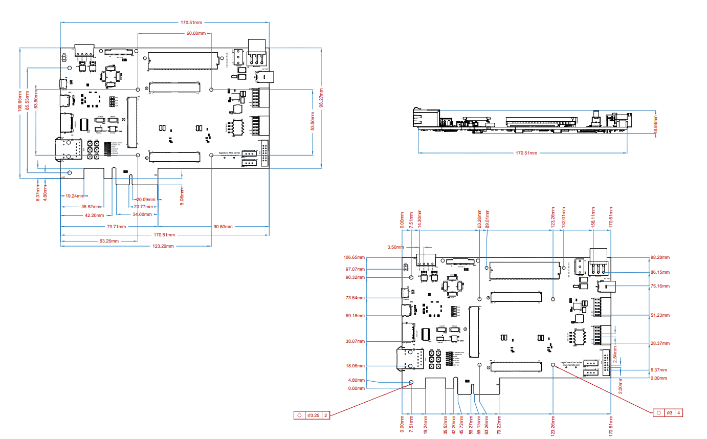
Physical Dimensions