Introduction
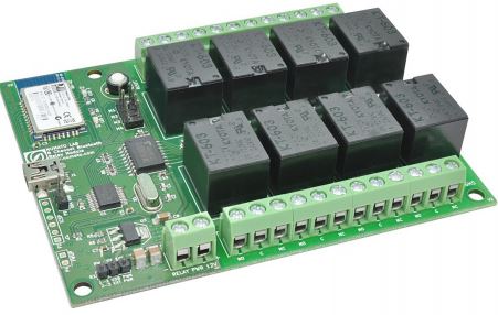 Numato Lab’s 8 Channel Bluetooth Relay Module is a versatile product for controlling electrical and electronic devices remotely from a PC over Bluetooth link. Ease of use and wider operating system compatibility are the primary goals behind this product’s design. This simplicity allows the use of off-the-shelf Terminal Emulation programs such as Hyper Terminal and PUTTY for controlling the module with a simple set of human-readable commands. For power users, this module can be controlled by writing programs in various programming languages.
Some of the possible uses of this module include
- Home Automation
- Lighting Control
- Garden Equipment Control
- Industrial Automation
- Test Fixtures
- DIY and Hobby
This product is compatible with the following operating systems.
- Windows XP and later
- Linux
- Mac
- And any other operating system that supports Bluetooth devices.
And these are some of the languages that can be used for programming.
- C/C++
- Visual Basic (VB6, VB2008, VB2010 express and other editions)
- Visual Basic for Applications (Microsoft Office VBA)
- Perl
- Python
- JAVA
- And many more…
This module has 8 onboard relays and associated drivers capable of controlling a large number of devices including lamps, motors, locks, etc… (Please see recommendations for using this product with inductive loads elsewhere in his document). This module also includes General Purpose I/Os, and analog inputs (multiplexed with GPIOs) that can be accessed over the Bluetooth interface for extended functionality. The module communicates with the host PC over the Bluetooth link. A USB Bluetooth Dongle or Bluetooth integrated PC/Laptop would be sufficient to communicate with this device. A USB connector is available onboard for firmware upgrade.
How to use the module
The following section describes how to use this module.
Components/Tools required
Along with the module, you may need the items in the list below for easy and fast installation.
- +12V 1A power supply
- Medium size Philips screwdriver
Connection Details

Connection Diagram
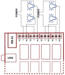
The above image shows the basic connection diagram that can be used in most of the situations. The connection diagram is the same for both AC and DC loads. Please make sure to use a freewheeling diode or snubber circuit if the load is inductive. More details about using inductive loads are available elsewhere in this document. It is important to make sure that the wires used to connect loads are sufficiently rated to handle the expected load current. Exercise caution while working with high voltages. Short circuits can cause damage to the module and the PC. The following sections identify individual connections in detail.
 This module provides 4 onboard jumpers (M1, M2, M3 & M4) for configuration of the Bluetooth module. The table below summarizes the Selection jumper and its function. Refer to RN42 Datasheet http://www.rovingnetworks.com/products/RN42 for more details.
| Jumper | Function | Default Jumper Position |
|---|---|---|
| M1 | Baud rate | Loaded |
| M2 | Auto connect | Unloaded |
| M3 | Auto pairing | Unloaded |
| M4 | Factory reset | Unloaded |
Reset
 The push-button labeled “RESET” is connected to reset pin of RN42 used for resetting the RN42 Bluetooth module
Bluetooth Interface
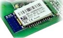 The onboard fully qualified RN-42 2.4GHz Bluetooth module that helps a PC/Linux/Mac computer to communicate and control this module seamlessly.
USB Interface
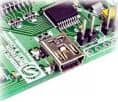
The onboard full-speed USB controller that helps a PC/Linux/Mac computer to program this module seamlessly. Use a USB A to Mini B cable to connect with a PC. Please visit the product page at http://www.numato.com to see available USB connector options (the picture on the right shows USB Mini B connector).
![]() Visit http://numato.com/cables-accessories to buy cables and accessories for this product.
Visit http://numato.com/cables-accessories to buy cables and accessories for this product.
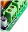
Relay Contacts
All contacts on each relay are available externally on screw terminals for easy user access. The relays are rated for AC  and DC supply voltages. Please see the electrical parameter table for more details. Each relay has three contacts(C, NO, and NC). C is the common terminal and is used in both normally open and normally closed positions. The contacts NC and C will be connected when the relay is turned off and will be disconnected when the relay is turned on. And vice versa, the contacts C and NO will be disconnected when relay is turned off and will be connected when the relay is turned on. The table below summarizes possible relay contact positions.
| Relay State | Connection between NC and C | Connection between NO and C |
|---|---|---|
| OFF | Close | Open |
| ON | Open | Close |
DC Power Supply
 This module uses two power supplies to function properly. A +5V supply for the logic circuit and a +12V supply for the relay coils. By default, the board is configured to use the +5V supply from External. So a USB +5V power is not required. The +12V supply for the relay coils is not optional and the relay will not switch without this supply. Any off the shelf 12V DC power supply can be used for this purpose. Make sure to connect the power supply in correct polarity. Connect the positive terminal of the power supply to the +12 terminal on the module. Connect the negative terminal of the power supply to the GND terminal of the module. Connecting power supply incorrectly can cause damage to the module and/or other devices.
If for any reason, USB 5V power supply needs to be used for the logic section of the module, the Power Select Jumper should be configured properly before connecting the power supply. Please refer to the marking on the board for more details. Make sure to connect the power supply with the correct polarity. Connect the positive terminal of the power supply to the +5V terminal on the module.
![]()
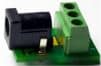 Using a product similar to Numato’s DC Barrel Jack Adapter is recommended if the power supply has a Barrel Jack connector (See the image on right).
Connecting power supply incorrectly can cause damage to the module and/or other devices.
GPIO/Analog inputs (optional connection)
In addition to onboard relays, this product has 2 General Purpose IO pins that can be used for 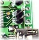 various custom applications. One of these pins can be used as Analog to Digital Converter inputs as well. All IO pins support 3.3V TTL signals and the ADC input range is 0 to +3.3V. The ADC can acquire analog signals at the resolution of 10 bits per sample. It is recommended to use a series resistor with the GPIO/ADC pins when interfacing with other circuits. In output mode, each GPIO can source up to 25 mA. So no additional circuitry is needed to drive regular LEDs. A 470 Ohms series resistor is recommended for current limiting when connecting LED to a GPIO
In contrast to GPIOs Analog inputs can read voltages at any level between 0 to 3.3 volts. It is recommended to use a series resistor to protect the input from stray voltages and spikes. The internal Analog To Digital converter supports 10 bits resolution which is adequate for most applications. The table below summarizes the GPIO and Analog to Digital Converter input positions on the header.
| Pin number on the header | GPIO | ADC |
|---|---|---|
| RB4 | IO0 | ADC0 |
| RB6 | IO1 | NA |
Driver Installation
Windows
When the 8 Channel Bluetooth Relay Module is Powerup for the first time a red LED(LED1) will toggle at 1 Hz in the board which means the module is discoverable and waiting for a connection. Then follow the below steps and images.
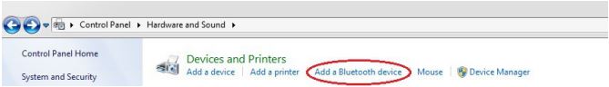
1. Go to Bluetooth Devices(Control PanelHardware and SoundDevices and PrintersBluetooth Devices)] on your PC.
Note: Please be sure that your PCLaptop having a driver installed USB Bluetooth dongle or Bluetooth integrated.
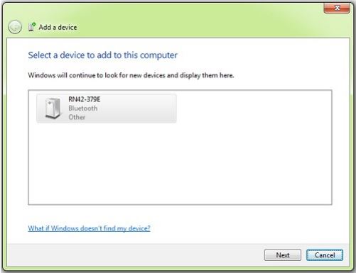
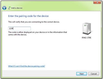
2. Select RN42 and click Next.
3. Select the second option(Enter the device’s pairing code).
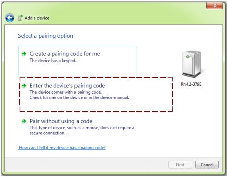
4. Enter the default pairing code “1234 “
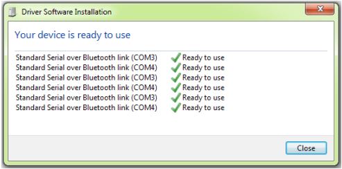
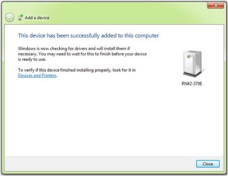
5. It will install the driver automatically(In windows7) as below
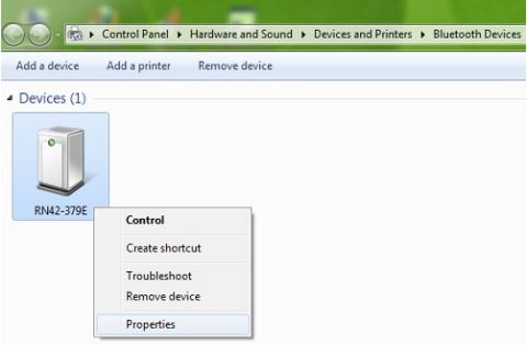
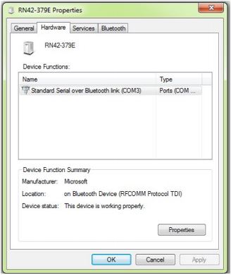
6.Right-click on the device(RN42), select Properties/Hardware. Note down the name of the serial port (COM1, COM2, etc..). This information is required to control the module from the PC.
Linux
To use this product with Linux, the Bluetooth device driver needs to be compiled in with the kernel. Fortunately, most Linux distributions (Ubuntu, Redhat, Debian, etc..) have this driver pre-installed. When connected to a Linux machine, this product should appear as a serial port in the /dev directory. Usually, the name of the device will be “rfcommx” or similar. The name may be different depending on the Linux distribution you have.
Mac
Similar to Linux, Mac operating system comes with the required drivers pre-installed. When connected to a Mac computer, the device should appear as a serial port
Sending Commands
One of the most powerful features of this module is the simple easy to use command set it supports. The following sections give details of the command set and how to use the command set.
The command set
This product supports a very simple command set that is designed to be less cryptic and easy to use manually (using serial terminal emulation programs) or through a program written in many supported languages.
List of currently supported commands
| No. | Command | Parameters | Example | Description |
|---|---|---|---|---|
| 1 | ver | None | ver | Returns firmware Version |
| 2 | id | get/set xxxxxxxx | Id get, id set 12345678 | Reads/Sets id of the module |
| 3 | relay | on/off/read, relay number readall/writeall | relay on 0,relay off 0, relay read 0, relay readall, relay writeall ff | Relay control |
| 4 | reset | None | reset | Reset relays to default state (all relays turned off) |
| 5 | adc | read, channel | adc read 0 | Read Analog to Digital Converter input |
| 6 | gpio | set/clear/read, gpio number | gpio set 0, gpio clear 0, gpio read 0 | Control General Purpose Input/Output |
The table below has more detailed information about available commands.
| No. | Command | Example | Description |
|---|---|---|---|
| 1 | ver | ver | Returns current firmware version. |
| 2 | id | id get id set xxxxxxxx | Id get reads the module ID. Id set will assign a new ID to the module. “x” stands for alphanumeric characters including symbols. The new ID must be exactly 8 characters in length. |
| 3 | relay | relay on x | Turns a particular relay on. The parameter “x“ stands for the relay number. The relay number starts from zero. See some examples below. relay on 0 – Turns on relay 0 relay on 1 – Turns on relay 1 |
| relay off x | Turns a particular relay off. The parameter “x“ stands for the relay number. The relay number starts from zero. See some examples below. relay off 0 – Turns off relay 0 relay off 1 – Turns off relay 1 |
||
| relay read x | Returns the status of a particular relay. The parameter “x“ stands for the relay number. The relay number starts from zero. See some examples below. relay read 0 – Returns status of relay 0 relay read 1 – Returns status of relay 1 The data returned in response to this command will be either “on” or “off” depending on the current status of the relay |
||
| relay readall | Reads the status of all relays in a single operation. The return value will a hexadecimal number with binary value 1 at bit positions for relays in ON state and 0 for relays in OFF state. Eg: a return value 00 (binary 0000 0000 ) means all relays are OFF. A value FF (binary 1111 1111 ) means all relays are ON. relay readall – Returns status of all relays |
||
| relay writeall xx | Control all relays in a single operation. A hexadecimal value must be specified with desired bit positions set to 0 or 1. A value 0 at a bit position will turn off the corresponding relay. A value 1 at a bit position will turn on the corresponding relay. relay writeall ff– Turns on all relays |
||
| 4 | reset | reset | Resets all relays to off state which is the default state. GPIOs are not by affected by the command. |
| 5 | adc | adc read x | Reads the analog voltage present at the ADC input mentioned.“x” stands for the number of ADC input. The response will be a number that ranges from 0 – 1023. Please see examples below. adc read 0 – Reads analog input 0 |
| gpio set x | Sets the GPIO output status to high. Here “x” is the number of the GPIO. Please see examples below. gpio set 0 – Sets GPIO 0 to high state |
||
| 6 | gpio | gpio clear x | Sets the GPIO output status to low. Here “x” is the number of the GPIO. Please see examples below. gpio clear 0 – Sets GPIO 0 to low state |
| gpio read x | Reads the digital status present at the input mentioned. Here “x” stands for the number of GPIO. The response will be either “on” or “off” depending on the current digital state of the GPIO. Please see examples below. gpio read 0 – Reads GPIO 0 status |
Controlling relays using Serial Terminal Emulator software
The simple set of ASCII based human-readable command set supported by this module makes controlling relays easy with any off the shelf Serial Terminal Emulation program like Hyper Terminal or Teraterm. The most important thing to remember here is that since the module appears as a serial port in the operating system, treat it just like any serial device you may use. Since the underlying transport is USB, not RS232, almost all settings such as baud rate, parity, number of stop bits can be left to the default values. Flow control needs to be set to “None”. The following sections give examples of how to use the module with Hyper Terminal and Teraterm.
Using this module with Hyper Terminal is very easy. Please follow the steps below.
- Connect the module to the computer, install Bluetooth driver and note down the name of the new serial port that appears RN42 in add new device window.
- Open Hyper Terminal and select the serial port corresponding to the relay module. Click OK.
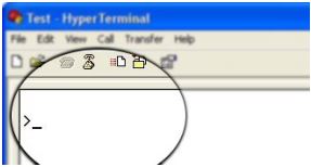
- If everything goes well, you should be presented with a blank screen. Press ENTER key and the command prompt should appear. Commands listed in the table above can be entered here now.
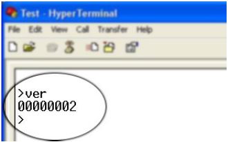
For example, here is the response to the “ver” command.
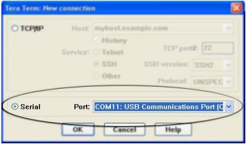
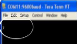
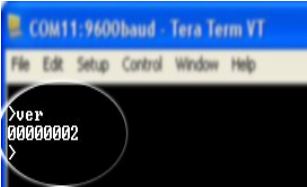
Using the relay module with Teraterm is just as easy. Please follow the steps below.
![]() Teraterm is an open-source software. A free copy can be downloaded from http://en.sourceforge.jp/projects/ttssh2/releases/
Teraterm is an open-source software. A free copy can be downloaded from http://en.sourceforge.jp/projects/ttssh2/releases/
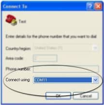
- Run Teraterm application and select the port corresponding to the relay module in the “New
connection” dialog and click OK.
- Press ENTER key on the main window and a command prompt should appear as in the image below
- Enter the command at the command prompt. Example “ver” command and response is in the image below
Controlling the module using a custom program
This relay module can be controlled using custom programs written in many languages. Almost any language can be used as long as it supports some sort of serial communication method. Some of the supported languages include
- C/C++
- Visual Basic
- Visual Basic for Applications (Microsoft Office VBA)
- Perl
- Python
- JAVA
- And a lot more…
The APIs that need to be used may be different depending on the target operating system even when the same language is used. For example, when using C/C++ on Windows, Win32 Serial Communication APIs along with File IO APIs (CreateFile, ReadFile, WriteFile, etc…) needs to be used (http://msdn.microsoft.com/en-us/library/ff802693.aspx). But when C/C++ is used on the Linux operating system “termios” APIs can be used for serial communication. Please refer to your compiler/language documentation for more details about serial port communication.
Specific details of programming may vary depending on the language and operating system of choice. But the fundamental steps for writing a program to control the relay module can be more or less the same. Here is the list of steps that you may need to follow while writing your own program.
- Open the serial port for communication.
- Set port parameters. Most of the parameters can be left to defaults except Flow Control, which needs to be set to “none”.
- To send a command to the module, use an API equivalent to write/writefile and pass the buffer/string containing the command. It is important to append Carriage Return (ASCII 13) to emulate the ENTER key.
- If return data is expected (Eg: “ver” command), try to read the characters from the serial port input buffer. APIs equivalent to Read/ReadFile can be used to read data from the module. Please note that the return data will include the command itself (since the module echoes everything back), the result, carriage return, and the “>” symbol.
Please visit the product page for available sample programs.
Additional Information
Analog to Digital Converter
8 Channel Bluetooth Relay Module do support Analog to Digital Conversion on some of the IO terminals. A list of GPIOs that supports analog function in this product is listed elsewhere in this document. There is no special command is required to execute to switch between analog and digital mode. Executing “adc” command will set the GPIO to analog mode and executing “gpio” command will set the GPIO back to digital mode on the fly. Resolution of the ADC is 10 bits unless otherwise noted. The input voltage range of the ADC is 0 – VDD (this product uses 3.3V power supply, so the range will be 0 – 3.3V). The result will be returned as a number starting at zero and ending at 1023. Zero indicates zero volts at the ADC input and 1023 indicates VDD (3.3V for this product) at ADC input.
Using GPIOs with switches
It is possible to read the position of a switch that is connected to a GPIO. An SPST or SPDT switch is recommended to 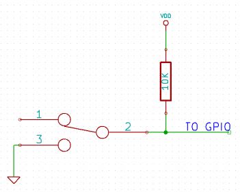 use with GPIOs. Push switches do maintain the contacts closed only for a very short time so using them is discouraged. The fundamental idea of using a switch with GPIO is to have the switch cause a voltage level change at the GPIO pin when pressed. Usually, this is achieved by using an external pull-up resistor along with the switch. The pull up resistor is connected between the GPIO and VDD and the switch is connected between the GPIO and ground. When the switch is not pressed, the pull-up resistor will cause the GPIO to stay at the VDD voltage level. When the switch is pressed, the GPIO is short-circuited to ground and stays at zero voltage. This change in voltage and thus the position of the switch can be read using the “gpio read” command. Please see the recommended connection diagram below
Using relay modules with inductive loads
It is important to take additional care when using relays with inductive loads. An inductive load is pretty much anything that has a coil and works based on magnetic principles like Motors, Solenoids, and transformers. Inductive loads produce back emf when the magnitude of the load current changes. The back emf can be in the order of tens or even hundreds of voltage (See this Wikipedia article http://en.wikipedia.org/wiki/Counter-electromotive_force). This effect is most severe when power is disconnected from the inductive load because the rate of change of current is maximum at that point. Even though the back emf lives only for a very short time (a few milliseconds) it can cause sparks between the relay contacts and can deteriorate the contact quality over time and reduce the life span for the relays considerably.
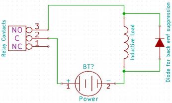
So it is important to take countermeasures to suppress the back emf to acceptable levels to protect relay contacts. Usually, this requires connecting electronic devices in parallel with the load such that they absorb the high voltage components generated by the load. For solenoids, connecting a diode (fast switching diode is recommended) in parallel to the load (in reverse direction to the load current) is very effective. A diode used for this purpose is usually called a freewheeling diode. Please see the diagram on the right for connection details.
A capacitor with a proper rating is recommended for protecting the relay contacts when a motor is used as a load. The capacitor should be rated enough to withstand the back emf that is generated by the motor. Please see the diagram below for connection details
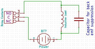
Please note that the relay modules are NOT shipped with back emf suppression devices pre-installed. The exact kind of suppression device and the parameters of the selected device can vary depending on the load itself. Some of the parameters that affect the suppression device selection are the inductance of the load, power supply voltage, load current, physical size/structure of the load, etc.. It is obvious that it is impossible for us to predict these parameters and design required back emf suppression device and incorporate that on the board. So we believe this is a task best left to the module user. There is an excellent article on designing back emf suppression on Wikipedia at http://en.wikipedia.org/wiki/Flyback_diode
Technical Specifications
| Parameter * | Value | Unit |
|---|---|---|
| Basic Specifications | ||
| Number of relays | 8 | |
| Number of GPIOs | 2 | |
| Number of analog inputs (Multiplexed with GPIOs) | 1 | |
| Digital circuit power supply voltage (USB or External) | 5 | V |
| Maximum current drawn by digital circuitry | 95 | mA |
| Bluetooth Specifications | ||
| Bluetooth version | Class 2 | |
| Baud rate speeds | 1,200bps to 921 Kbps | |
| Bluetooth range | 10 | m |
| Frequency | 2,402 ~ 2,480 | MHz |
| Communication Interface | SPP or HCI | |
| SPP data rates | 240 Slave 300 Master | Kbps Kbps |
| Supply voltage (DC) | 3-3.6 | V |
| IO Specifications | ||
| Maximum IO source current | 25 | mA |
| Maximum IO sink current | 25 | mA |
| GPIO input low voltage | 0.15 | V |
| GPIO input high voltage | 3.3 | V |
| GPIO output low voltage | 0 | V |
| GPIO output high voltage | 3.3 | V |
| ADC Specifications | ||
| Resolution | 10 | bits |
| Full scale range | 0 – VDD | V |
| Reference voltage | VDD | V |
| Recommended Impedance of Analog Voltage Source | 2.5 | KΩ |
| Relay Specifications | ||
| Nominal relay coil voltage | 12 | V |
| Nominal coil power consumption (per relay) | 360 | mW |
| Relay contact material | Silver Alloy | |
| Contact rating | 1C: 7A 240VAC/ 10A 120VAC | |
| Maximum switching voltage | 250VAC/ 30VDC | |
| Maximum switching current | 10 | A |
| Maximum switching power | 2770VA/ 240W | |
| Contact resistance (initial) | 100 Min at 6VDC 1A | mΩ |
| Life expectancy (Electrical) | 100,000 | Operations |
| Life expectancy (Mechanical) | 10,000,000 | Operations |
| Nominal insulation resistance | 100 Min at 500VDC | MΩ |
| Maximum switching on response time | 10 | mS |
| Maximum switching off response time | 5 | mS |
*All parameters considered nominal. Numato Systems Pvt Ltd reserve the right to modify products without notice.
* http://kyotarelays.com/datasheets/KT%20603.pdf
FAQ
Q. I set a GPIO to a particular value (0/1) using the “gpio set” command. When I read the same GPIO status later using the “gpio read” command I receive a different value than that I set. What is happening?
A. The “gpio read” command does not read the last value set to the GPIO by the user. Rather, it reads the actual digital voltage present at the GPIO pin from an external source. This could be different from what you have set previously.
Q. The GPIO loses its previously set value when trying to read the status. Why it is so?
A. When a gpio is to output a value (high/low), that particular GPIO is put to output mode. When you are trying to read the GPIO, it needs to be put in input mode. In input mode, the GPIO will go to a high impedance state and thus looses the previously set value.
Q. I’m using x language for programming. How do I find out if this language can be used to program and control the relay module?
A. Find out if the language of interest supports some kind of APIs/Functions/Components for serial communication. If it does, most likely you should be able to use that language with this module.
Q. What is the connector marked as ICSP on this module?
A. This connector is used to program the onboard microcontroller. This connector is primarily intended for factory use.
Q. I need a customized version of this product, can Numato do the customization for me?
A. Yes, we can definitely do customization but there may be minimum order requirements depending on the level of customization required. Please write to sales@numato.com for a quote.
Q. Where can I buy this product?
A. All Numato products can be ordered directly from our web store http://www.numato.com. We accept major credit cards and Paypal and ship to almost all countries with a few exceptions. We do have distributors in many countries where you can place your order. Please find the current list of distributors at http://numato.com/distrib.
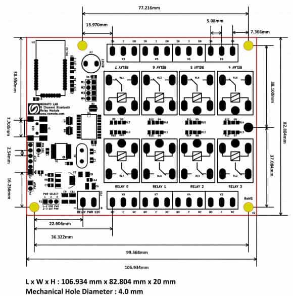
Mechanical Dimensions