Introduction
Numato Lab’s 16 Channel WiFi Relay Module is a versatile product for controlling electrical and electronic devices remotely from a PC through WiFi. This module comes with lowpower, 2.4 GHz, IEEE 802.11-compliant MRF24WG0MA WiFi radio transceiver module. It has an integrated PCB antenna and matching circuitry. Ease of use and wider operating system compatibility are the primary goals behind this product’s design. This simplicity allows use of off-theshelf Terminal Emulation programs such as Hyper Terminal and Tera Term for controlling the module with a simple set of human readable commands through Telnet or through easy to use Web interface. For power users, this module can be controlled by writing programs in various programming languages.
Applications
- Home Automation
- Industrial Automation
- Lighting Control
- Garden Equipment Control
- Consumer Electronics
- Remote Device Management
- Test Fixtures
- DIY and Hobby
Board Features
- Microcontroller: Microchip PIC32MX795F512L controller with 512K Flash.
- Memory: Microchip 25LC1024 serial EEPROM provides 1024 Kbits of storage for both web pages and nonvolatile configuration.
- WiFi: MRF24WG0MA, IEEE 802.11 b/g WiFi radio transceiver module with serialized unique MAC address.
- Serial: FT234XD USB to serial UART interface for WiFi Configuration Settings and firmware upload.
- Password protected Web console, Telnet and UART communication interface.
- Individual DIP switch channels for Firmware upload, WiFi configuration, Factory reset and Network Reset.
- The MRF24WG0MA module have radio regulation certification for United States (FCC), Canada (IC), and Europe (ETSI).
- LED indication for Power, Configuration and individual relay status.
- Relay: 16 SPDT Relays with individual LEDs for status.
- GPIO: 8 GPIOs, each can be configured as analog inputs with 10 bit resolution.
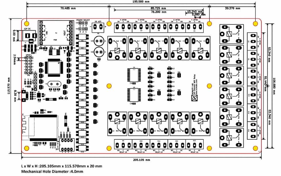
- Board Dimension: 205.105 mm x 115.570 mm.
How to Use the 16 Channel Wifi Relay Module
Components/Tools Required
Along with the module, you may need the items in the list below for easy and fast installation.
1. 12V 2A DC power supply.
2. Wireless Router.
3. Medium size screw driver.
Connection Diagram
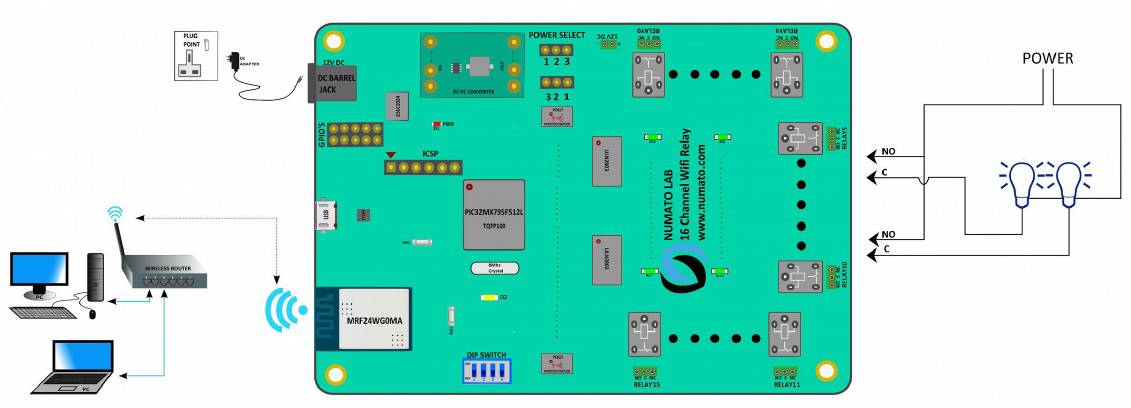
Above image shows basic connection diagram that can be used in most of the situations. The following sections identify individual connections in detail.
WiFi Interface
The on-board WiFi supports up to 54 Mbps transmission speed that helps a computer/smart phone to communicate and control this module easily. This board can be connected to a network in two ways.
- Change the device’s SSID and Password to match that of the host wireless router.
- Change the host wireless router’s SSID and Password to match that of the device SSID and Password.
First method is always recommended since the second method could interrupt network availability to other connected users. Changing 32 Channel WiFi GPIO Module’s SSID and Password is explained in the section 3. Configuring 16 Channel WiFi Relay Module.
The factory default WiFi settings of the board is given below.
| WiFi SSID | numato |
| WiFi Password | admin123 |
| WiFi Security Mode | 2(WPA2 with Pass Phrase) |
| Telnet Authentication | 1(Enabled) |
| Telnet Port | 23 |
| IP Filter | Disabled |
| MAC Filter | Disabled |
| GPIO Input Change Notify | Disabled |
Relay Contacts
All contacts on each relay is available externally on screw terminals for easy user access. The relays are rated for AC and DC supply voltages. Please see the electrical parameter table for more details. Each relay has three contacts(C, NO 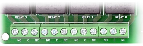 and NC). C is the common terminal and is used in both normally open and normally closed positions. The contacts NC and C will be connected when the relay is turned off and will be disconnected when relay is turned on. And vice versa, the contacts C and NO will be disconnected when relay is turned off and will be connected when the relay is turned on. Table below summarizes possible relay contact positions.
| Relay State | Connection between NC and C | Connection between NO and C |
|---|---|---|
| OFF | Close | Open |
| ON | Open | Close |
DC Power Supply
 This board can be operate with a single DC power supply. Use a 12V 2A DC power supply on DC jack(J1/Vin) on the Board for logic circuit.
DIP Switch Configuration
A 4 channel DIP switch(U4) on the board is used for doing four different operations. Be careful and know what will happens when each channel position is turn ON.
| DIP Switch Channel | Operation |
|---|---|
| 1 | Firmware Upgrade |
| 2 | WiFi Configuration |
| 3 | Factory Reset |
| 4 | Network Settings Reset |
By default the board will shipped with all switch channels in OFF position. WiFi configuration, Factory reset and Network settings reset are explained in page no:10.
Configuring 16 Channel WiFi Relay Module
Follow the below steps for setting new wireless SSID and Password.
1. Connect power and USB micro cable to the module.
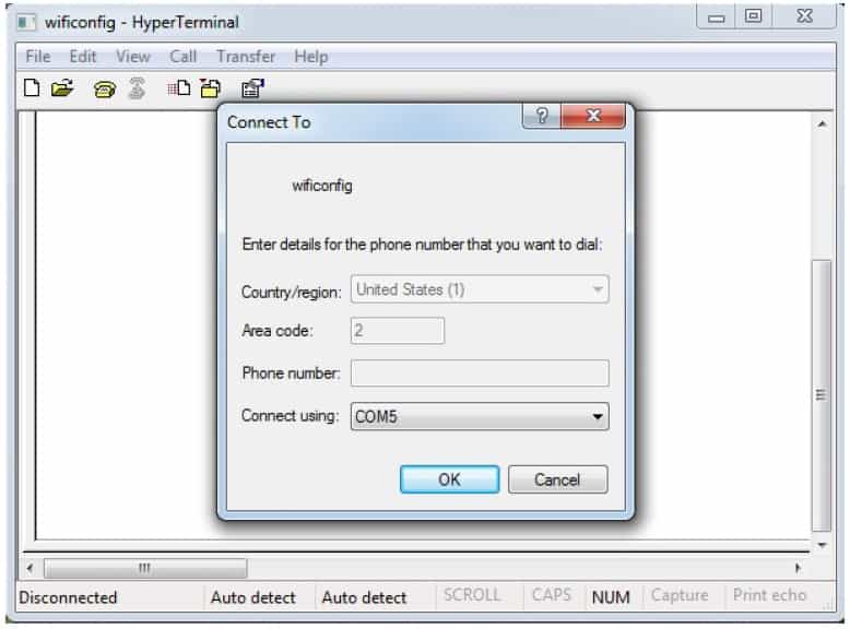
2. Open Hyper Terminal and connect corresponding COM port as shown below.
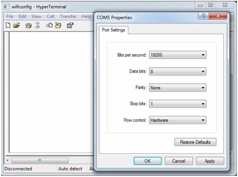
3. Change the Port Settings by clicking Restore Defaults. Then change the Bits per second to 19200 and select OK.
4. Change the DIP switch(U4 on board) 2nd channel to ON state. Then press the push button SW2
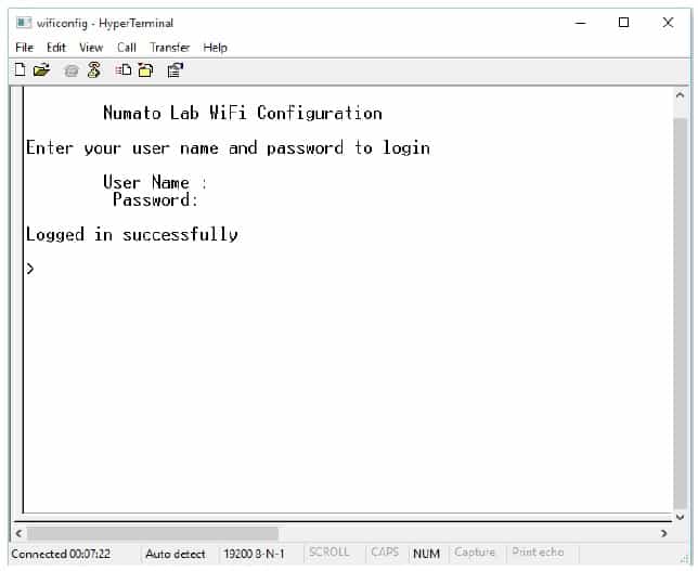
for a second, immediately the terminal window will refresh as follows.
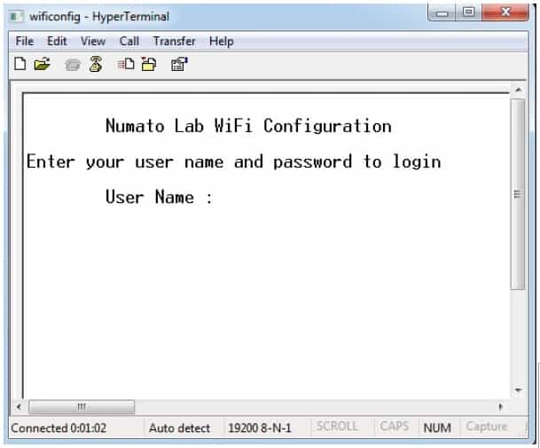
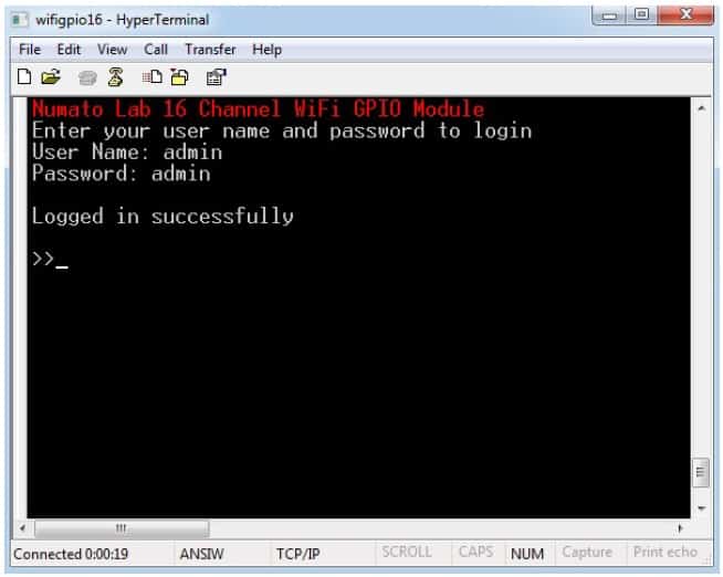
5. The typed User name and Password will not be visible until login successfully. Type the User
name as ‘admin‘ and press enter key.
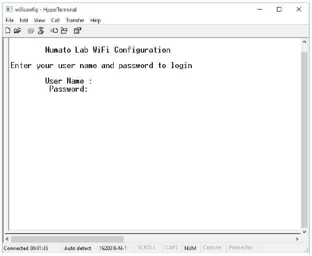
6. Type the Password as ‘admin‘ and press enter key. If both are typed correct, then window will refresh as below.
NOTE: User name and Password are case sensitive
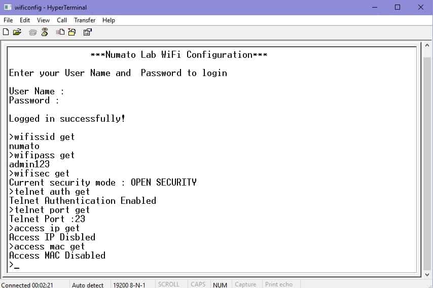
7. Type the following commands on the table for getting factory default WiFi settings as below.
| Command | Description |
|---|---|
| wifissid get | wifissid get reads the module SSID. Factory default SSID is 'numato' |
| wifipass get | wifipass get reads the module Password. Factory default Password is 'admin123' |
| wifisec get | wifisec get reads the module security mode. Factory default security is 2, 'WPA2 with Pass Phrase' |
| telnet auth get | telnet auth get command reads the current authentication setting. Factory default authentication is 'enabled'. |
| telnet port get | telnet port get command reads the current telnet port. Factory default telnet port is '23'. |
| access ip get | access ip get command reads the IP filter is enabled or disabled. Factory default access IP status is 'disabled'. Using 'access ip' command group we can filter access to the module. When access ip is enabled, this command returns the stored 10 number of IPs, IP0 to IP9, if it is disabled then it will return the IPs as 255.255.255.255. |
| access mac get | access mac get command reads the MAC filter is enabled or disabled. Factory default access MAC status is 'disabled'. Using 'access mac' command group we can filiter access to the module. When access MAC is enabled, this command returns stored 10 number of MAC, MAC0 to MAC9, if it is disabled then it will return the MAC as FF FF FF FF FF |
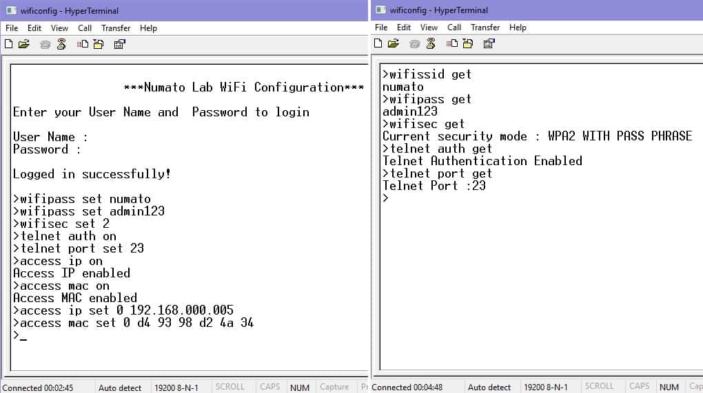
8. The configuration settings can be set by the following commands.
| Command | Description |
|---|---|
| wifissid set xxxxxxxx | wifissid set will assign a new SSID to the module. “x” stands for alphanumeric characters including symbols. The new User name can be 1 – 32 characters length. See the example below. wifissid set 16channelgpio |
| wifipass set xxxxxxxx | wifipass set will assign a new Password to the module. “x” stands for alphanumeric characters including symbols. The new Password can be 8 – 32 characters length. Minimum Password length is 8 characters. See the example below. wifipass set 2345678 |
| wifisec set x | wifisec set x command will set different security modes. Here 'x' stands for the mode, 0 to 3. 0 represents Open 1 represents WPA with Pass Phrase. 2 represents WPA2 with Pass Phrase. 3 represents WPA/WPA2 with Auto Pass Phrase. Eg: wifisec set 0 |
| telnet auth on/off | telnet auth on/off command sets the authentication for telnet operation. 'telnet auth on' enable the authentication for Telnet connection, if the telnet authentication is enabled then user must enter the login credentials by default username and password is 'admin'. 'telnet auth off' disables the authentication for Telnet connection. Eg: telnet auth off |
| telnet port set xx | telnet port set xx command sets the Telnet port. Here 'xx' stands for the port number in the range of 00 to 99. By default, port number is 23 Eg: telnet port set 45 |
| access ip on/off | access ip on/off command enable/disable the IP filter operation. If the access IP is enabled, then maximum 10 number of IPs can communicate with the module and we can set these IPs using 'access ip set N' command. By default, access IP is disabled Eg: access ip on |
| access mac on/off | access mac on/off command enable/disable the MAC filter operation. If the access mac is enabled, then maximum 10 number of MAC can communicate with the module and we can set these MAC using 'access MAC set N' command. By default, access MAC is disabled. Eg: access mac on |
| access ip set N xxx.xxx.xxx.xxx | access ip set N xxx.xxx.xxx.xxx commands adds the IP address to access IP filter table. Here 'N' stands for the IP number 0 to 9 in the filter table. 'xxx.xxx.xxx.xxx' stands for IP address we can store in the filter table. Eg: access ip set 0 192.168.000.005 |
| access mac set N xx xx xx xx xx xx | access mac set N xxx.xxx.xxx.xxx commands adds the MAC address to access MAC filter table. Here 'N' stands for the MAC number 0 to 9 in the filter table. 'xx.xx.xx.xx' stands for MAC address we can store in the filter table, only hex values are allowed. Eg: access mac set 0 D2 7E 88 1E AD AA |
9. Execute wifissid set, wifipass set, wifisec set, telnet auth set, telnet port set as follows for the new configuration settings, recommend to confirm the new settings saved using wifissid get, wifipass get, wifisec get, telnet auth get, telnet port get, access ip get, access mac get commands.
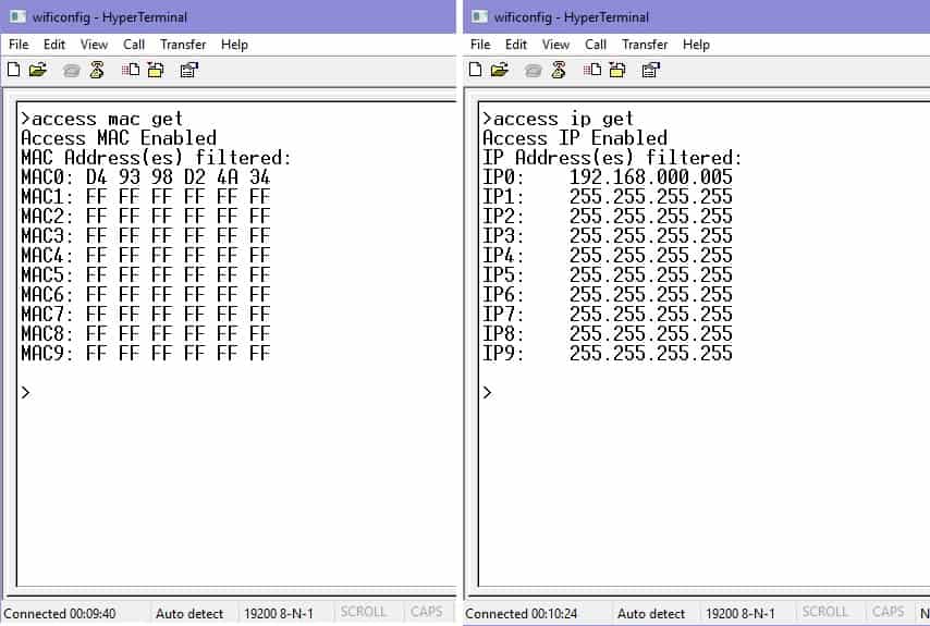
10. Below image shows the IP filter and MAC filters are enabled and displays the filtered MAC and IP address.
11. If the new configuration settings are saved, change the DIP switch(U4 on board) second channel back to OFF state. Then press the reset push button SW2 for a second again. If everything is fine the terminal window will displays the configuration details, connection status and module’s IP.
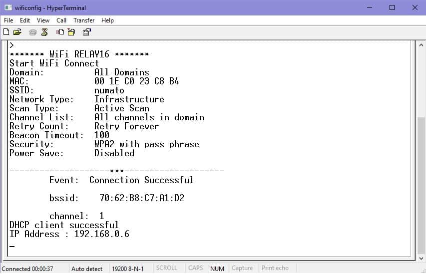
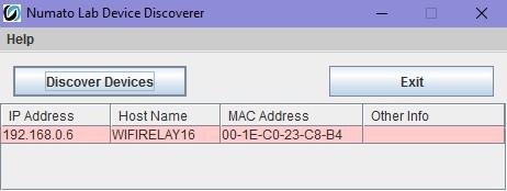
12. If the status shows DHCP client successful as above, now the board is ready to use. Run Numato Lab Device Discoverer.jar. The window will displays the IP address, Host Name, MAC Address and Other information.
13. Now Power off the device and remove USB micro cable. Once configuration is successfully completed , the USB cable is not necessary for the functioning of board. Powering up and accessing the module is explained in section 6. Powering Up 16 Channel WiFi Relay Module.
Factory Reset
To execute factory reset, please follow the steps below.
- Connect the power and change the DIP switch(U4 on board) 3rd channel to ON state.
- Press the push button SW2 near the USB micro connector for a second and wait for 5-10 seconds until Led D2 blinks.
- Change the DIP switch(U4 on board) 3rd channel to OFF state. Then press the push button SW2 again for a second to reset the firmware.
This action will reset User name, Password, Device ID, WiFi SSID, Password and also other settings as well. After reset the board can be accessed using the default User name and Password. The factory default settings will be as below table.
| Device ID | 00000000 |
| User name | admin |
| Password | admin |
| Wifi SSID | numato |
| Wifi Password | admin123 |
| Wifi security mode | 2 ( WPA2 with Pass Phrase) |
| Telnet authentication | Enabled |
| Telnet port | 23 |
| Access IP | Disabled |
| Access MAC | Disabled |
| GPIO interrupt notify | Disabled |
Network Settings Reset
To execute network settings reset, please follow the steps below.
- Connect the power and change the DIP switch(U4 on board) 4th channel to ON state.
- Press the push button SW2 near the USB micro connector for a second and wait for 5-10 seconds until Led D2 blinks.
- Change the DIP switch(U4 on board) 4th channel to OFF state. Then press the push button SW2 again for a second to reset the firmware.
This action will reset Network settings such as Host name and IP address. DHCP will also enabled after
network settings reset. The factory default network settings will be as below table.
| Host Name | WIFIRELAY16 |
| IP Address | DHCP Enable |
Powering Up 16 Channel WiFi Relay Module
Connect a DC power supply and power up the device as mentioned DC Power Supply section above. The LED (D1) will glow which indicates active power. Connect the module in a network as explained in WiFi configuration settings. Then run Numato Lab Device Discoverer.jar (Java Runtime must be installed on the target machine), click on Discover Devices. The window will displays the IP address, Host Name, MAC Address and Other information.
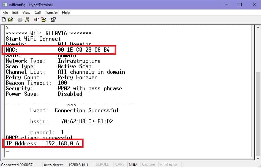
IP Address and MAC Address can see in UART configuration window, Open Hyper Terminal and connect corresponding COM port as explained in the above section 3.Configuring 32 Channel WiFi GPIO module. Press the reset button ‘SW1’ check the results on the window.
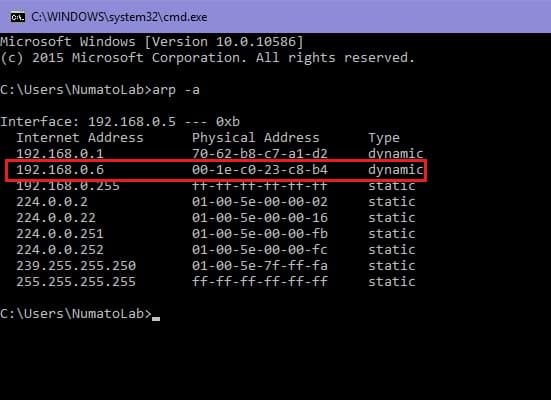
IP Address and MAC Address can be found using arp command also, open the command prompt and type the command ‘arp -a‘. This will display the available network interfaces and connected devices along with the MAC address and IP address of each device. Look for the IP address that corresponds to your device’s MAC address.
Accessing the Module
The module can be controlled by using one of the two interfaces below.
1. Through HTML/Web Page served from the device.
2. Through a Serial terminal Emulator that supports TELNET (Eg: Hyper Terminal, Tera Term, PUTTY..).
Accessing the Module Using Web Interface
The easiest method for controlling the module is through web page served from the device. To open the administration web page, type in the IP address in to the address bar of any web browser and press enter.
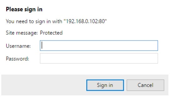
You will prompted to enter User name and Password. The default User name and Password is ‘admin‘.
You may change the User name and Password once logged in.
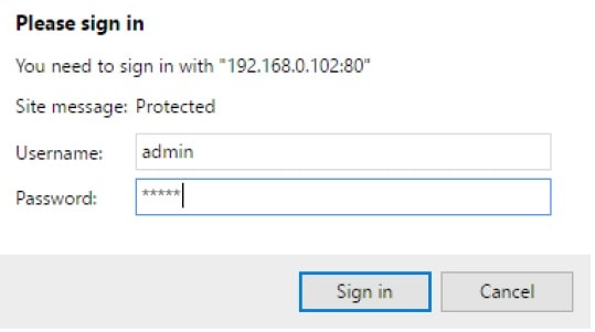
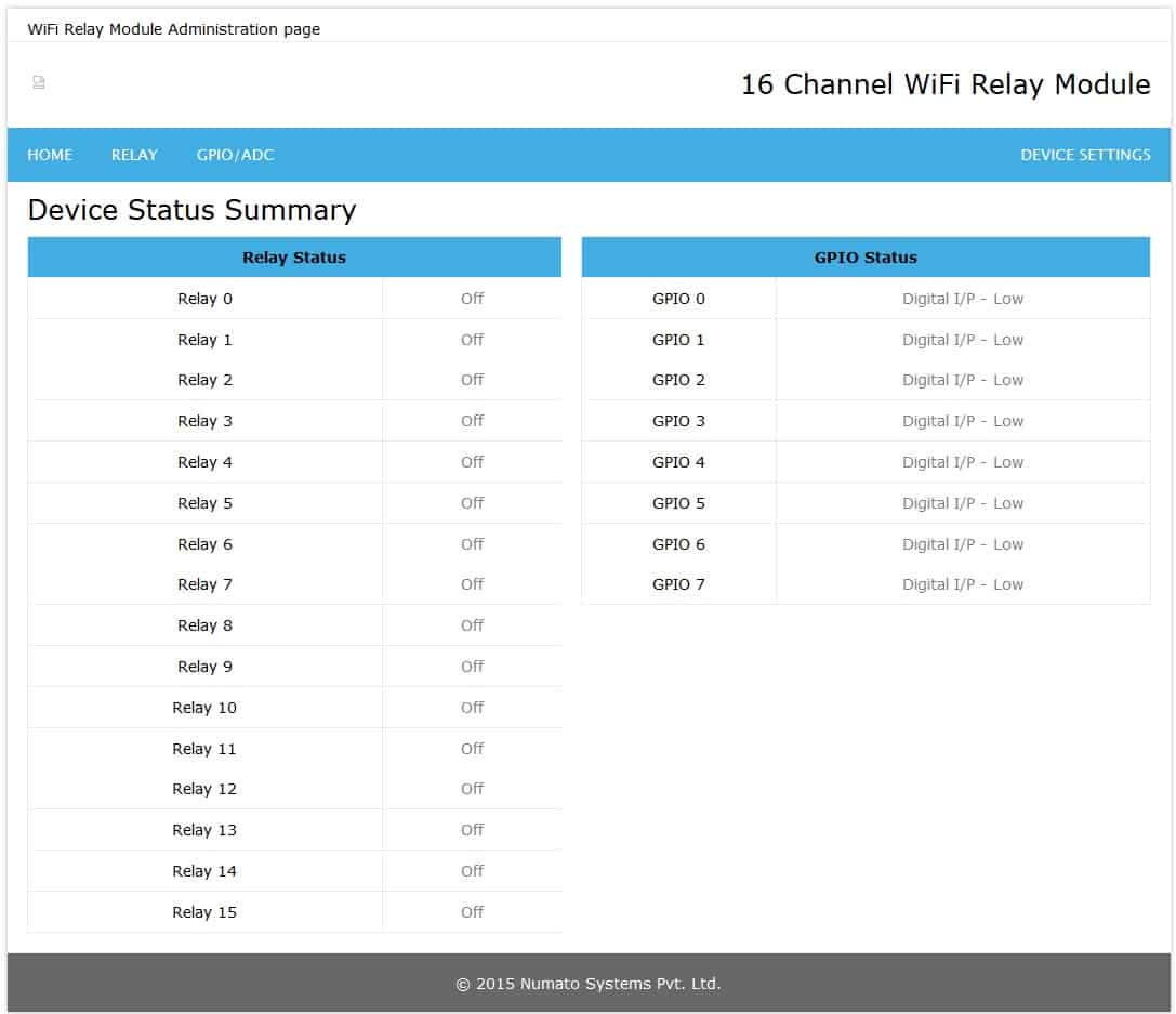
Enter the default User name and Password then click OK. You will be presented with the device home
page that shows the status of Relays and GPIOs.
NOTE: Web page, UART(WiFi configuration) and telnet shares the same User name and Password. Any changes to any of this will affect these three security settings.
Relay Status and Control
There are 16 SPDT relays on the board that can be controlled over Ethernet. Click on the “Relay” link on the menu bar to access Relay configuration page. The ‘Relay Index’ shows the corresponding relay on board. Relays on the board can be turned on/off by clicking the ‘Toggle Relay’ button next to the corresponding relay index. The ‘Status’ of the relays change automatically for easy identification.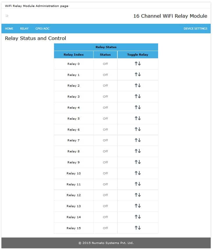
GPIO Status and Control
This board has 10 general purpose input/output’s each multiplexed with analogue input. Click on the GPIO/ADC link on the menu bar to access GPIO configuration page. The GPIOs can be turned on/off by clicking on the Toggle GPIO button next to the corresponding GPIO.
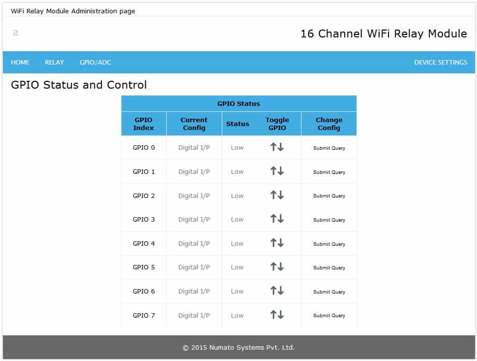
Individual GPIO can be configured in three modes.
1. Digital Input(I/P)
2. Digital Output(O/P)
3. Analog Input
Individual GPIOs on the board can be turned on/off by clicking the ‘Toggle GPIO’ button next to the corresponding index. The status change will be displayed on the page immediately for feedback.
 All GPIO pins can be used as Analog to Digital Converter inputs as well. The ADC input range is 0 to +3.3V. The ADC can acquire analog signal at the resolution of 10 bits per sample. It is recommended to use a series resistor with the GPIO/ADC pins when interfacing with other circuits.In output mode, GPIOs can source up to 25mA.
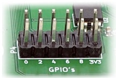
The table below summarizes the GPIO and Analog to Digital Converter input positions on the header.
| GPIO | ADC |
|---|---|
| 3V3 | 3V3 |
| 3V3 | 3V3 |
| IO0 | ADC0 |
| IO1 | ADC1 |
| IO2 | ADC2 |
| IO3 | ADC3 |
| IO4 | ADC4 |
| IO5 | ADC5 |
| IO6 | ADC6 |
| IO7 | ADC7 |
| GND | GND |
| GND | GND |
Device Settings
Device Settings page displays the current firmware version, Device ID, Account Settings, Basic Network Settings and WiFi Setings. A logged in user can change and save the Device ID, User name, Password and network settings.
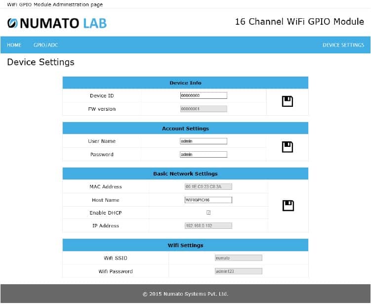
In the above image, firmware version is displayed as 00000001, default device ID 00000000, default User name and Password as ‘admin’. The user can change and save the Device ID, User name and Password as explained in command set (Page No.23) or changing the appropriate field on this page and clicking on the save button on right side. The User name and Password can be reset to factory defaults via Factory Reset explained elsewhere in this document. The Basic Network Settings Shows the Device MAC address, Host Name and IP Address. The default host name and IP Address can also be changed according to the user wish. After saving changes the board will reboot with the new network settings. WiFi Setting can’t be changed from here.
Controlling the Module Through TELNET Interface
The simple set of ASCII based human readable command set supported by this module makes controlling GPIOs easy via TELNET protocol very easy. The following sections give examples of how to use the module with Hyper Terminal and Tera Term.
To use this module with Hyper Terminal, please follow the steps below.
- Connect the module in a WiFi enabled network.
- Open Hyper Terminal and enter the IP address corresponding to the module, leave the port number as 23.
- Click OK.
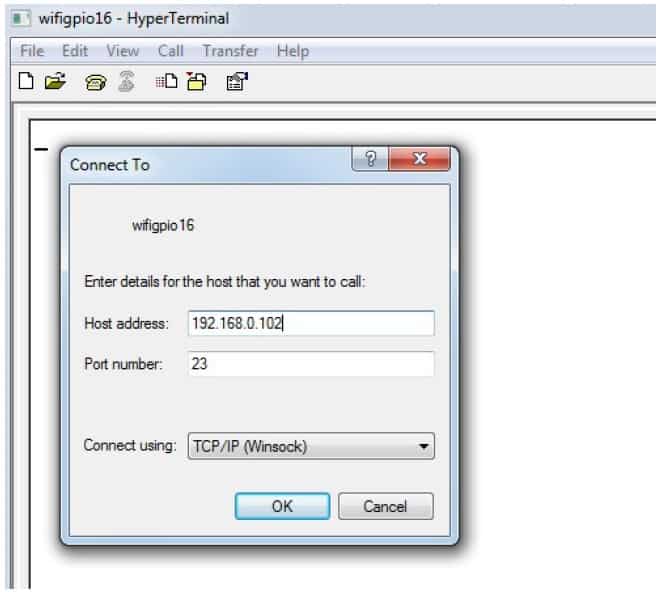
- If everything goes well, you should be presented with a screen as below.
- Select the properties button and do as same as shown below, then press OK.
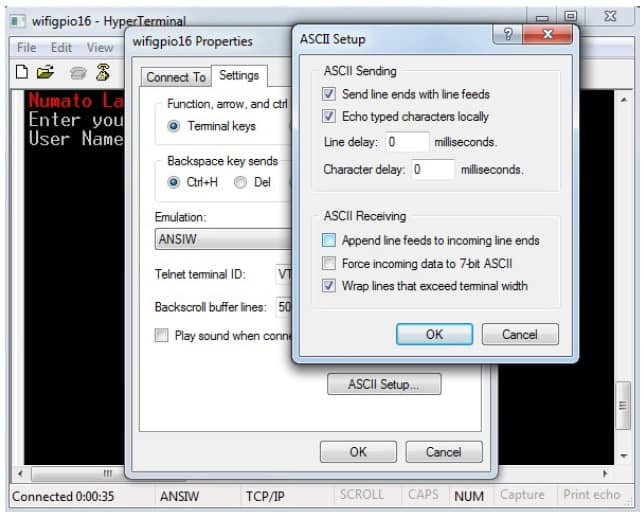
- Type in the TELNET User name and Password when asked and press enter key.
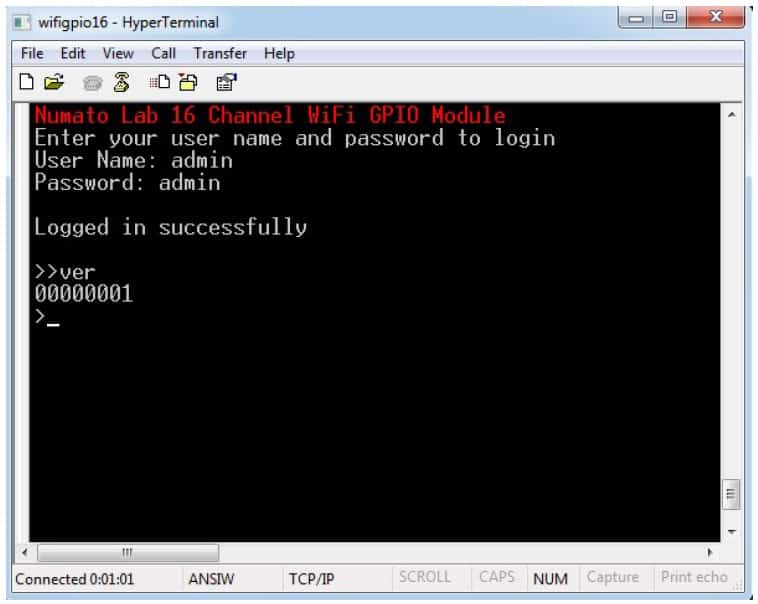
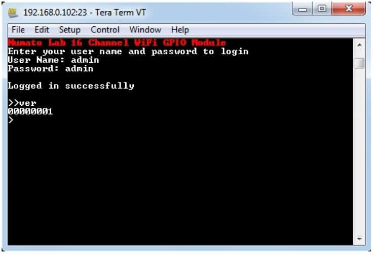
- Press ENTER key again and the command prompt should appear. Commands listed in the table
below (please see section “Sending Commands”)can be entered here now. For example, here is
the response for “ver” command.
Using the GPIO module with Tera Term is just as easy. Please follow the steps below.
Tera Term is an open source software. A free copy can be downloaded from http://en.sourceforge.jp/projects/ttssh2/releases/
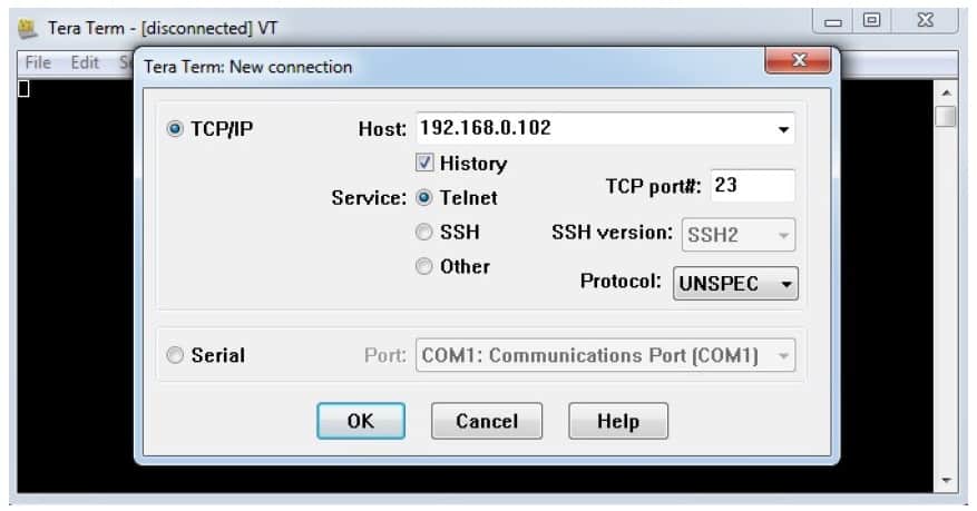
- Run Tera Term and type in the IP address corresponding to the module in the “New
connection” dialog and click OK.
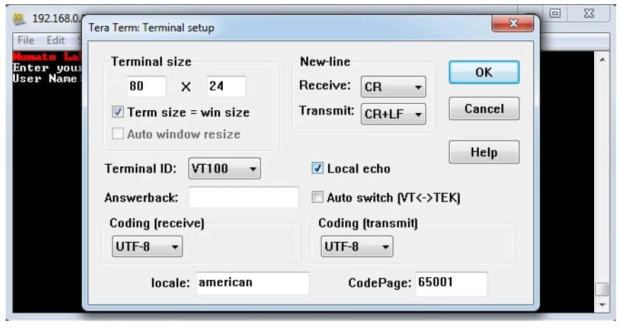
- Then select the terminal setup from the setup button and make sure the settings are as shown
below, and press OK.
- Type the User name and Password when asked.
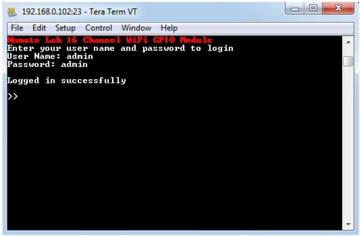
- Press ENTER key and the command prompt should appear. Commands listed in the table below
(please see section “Sending Commands”) can be entered here now. For example, here is the
response for “ver” command.
Sending Commands
One of the most powerful features of this module is the simple easy to use command set it supports. This command set allows for a very simple interface to access the features of the module through TELNET protocol. The following sections give details of the command set and how to use the command set.
The command set
This product supports a very simple command set that is designed to be less cryptic and easy to use manually (using terminal emulation programs that support TELNET) or through a program written in one of the many supported languages.
List of currently supported commands.
| No. | Command | Parameters | Example | Description |
|---|---|---|---|---|
| 1 | ver | None | ver | Returns firmware Version |
| 2 | id | get/set xxxxxxxx | id get, id set 12345678 | Reads/Sets id of the module |
| 3 | usr | get/set xxxxxxxx | usr get, usr set admin | Reads/Sets user name |
| 4 | pass | get/set xxxxxxxx | pass get, pass set admin | Reads/Sets password |
| 5 | relay | on/off/read, relay number readall/writeall | relay on 0, relay off 0, relay read 0, relay readall, relay writeall ff | Relay control |
| 6 | reset | None | reset | Reset relays to default state (all relays turned off) |
| 7 | adc | read, channel | adc read 0 | Read Analog to Digital Converter input |
| 8 | gpio | set/clear/read, gpio number | gpio set 0 | Control General Purpose Input/Output |
The table below has more detailed information about available commands.
| No. | Command | Example | Description |
|---|---|---|---|
| 1 | ver | ver | Returns current firmware version. |
| 2 | id | id get id set xxxxxxxx | Id get reads the module ID. Id set will assign a new ID to the module. “x” stands for alphanumeric characters including symbols. The new ID must be exactly 8 characters in length. |
| 3 | usr | usr get usr set xxxxxxxx | usr get reads the default user name. usr set will assign a new usr name to the module. “x” stands for alphanumeric characters including symbols. The new user name can be 1 – 8 characters length. |
| 4 | pass | pass get pass set xxxxxxxx | pass get reads the default password. pass set will assign a new password to the module. “x” stands for alphanumeric characters including symbols. The new password can be 1 – 8 characters length. |
| 5 | relay | relay on x | Turns a particular relay on. The parameter “x” stands for the relay number. The relay number starts from zero. See some examples below. relay on 0 – Turns on relay 0 relay on 1 – Turns on relay 1 |
| relay off x | Turns a particular relay off. The parameter “x” stands for the relay number. The relay number starts from zero. See some examples below. relay off 0 – Turns off relay 0 relay off 1 – Turns off relay 1 |
||
| relay read x | Returns the status of a particular relay. The parameter “x” stands for the relay number. The relay number starts from zero. See some examples below. relay read 0 – Returns status of relay 0 relay read 1 – Returns status of relay 1 The data returned in response to this command will be either “on” or “off” depending on the current status of the relay. |
||
| relay readall | Reads the status of all relays in a single operation. The return value will a hexadecimal number with binary value 1 at bit positions for relays in ON state and 0 for relays in OFF state. Eg: a return value 00 (binary 0000 0000) means all relays are OFF. A value FF (binary 1111 1111) means all relays are ON. relay readall – Returns status of all relays |
||
| relay writeall xx | Control all relays in a single operation. A hexadecimal value must be specified with desired bit positions set to 0 or 1. A value 0 at a bit position will turn off the corresponding relay. A value 1 at a bit position will turn on the corresponding relay. relay writeall ff – Turns on all relays |
||
| 6 | reset | reset | Resets all relays to off state which is the default state. GPIO's are not by affected by the command. |
| 7 | adc | adc read x | Reads the analog voltage present at the ADC input mentioned. “x” stands for the number of ADC input. The response will be a number that ranges from 0 – 1023. Please see examples below. adc read 0 – Reads analog input 0 adc read 2 – Reads analog input |
| 8 | gpio | gpio set x | Sets the GPIO output status to high. Here “x” is the number of the GPIO. Please see examples below. gpio set 0 – Sets GPIO 0 to high state gpio set 2 – Sets GPIO 2 to high state |
| gpio clear x | Sets the GPIO output status to low. Here “x” is the number of the GPIO. Please see examples below. gpio clear 0 – Sets GPIO 0 to low state gpio clear 2 – Sets GPIO 2 to low state |
||
| gpio read x | Reads the digital status present at the input mentioned. Here “x” stands for the number of GPIO. The response will be either “on” or “off” depending on the current digital state of the GPIO. Please see examples below. gpio read 0 – Reads GPIO 0 status gpio read 2 – Reads GPIO 2 status |
Additional Information
Analog to Digital Converter
16 Channel WiFi Relay Module do support Analog to Digital Conversion on some of the IO terminals. A list of GPIO’s that supports analog function in this product is listed elsewhere in this document. There is no special command is required to execute to switch between analog and digital mode. Executing “adc” command will set the GPIO to analog mode and executing “gpio” command will set the GPIO back to digital mode on the fly. Resolution of the ADC is 10 bits unless otherwise noted. The input voltage range of the ADC is 0 – VDD (this product uses 3.3V power supply, so the range will be 0 – 3.3V). The result will be returned as a number starting at zero and ending at 1023. Zero indicates zero volts at the ADC input and 1023 indicates VDD (3.3V for this product) at ADC input.
Using GPIO's with Switches
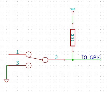
It is possible to read the position of a switch that is connected to a GPIO. A SPST or SPDT switch is recommended to use with GPIO’s. Push switches do maintain the contacts closed only for a very short time so using them is discouraged. The fundamental idea of using a switch with GPIO is to have the switch cause a voltage level change at the GPIO pin when pressed. Usually this is achieved by using an external pull-up resistor along with the switch. The pull up resistor is connected between the GPIO and VDD and the switch is connected between the GPIO and ground. When the switch is not pressed, the pull-up resistor will cause the GPIO to stay at VDD voltage level. When the switch is pressed, the GPIO is short circuited to ground and stays at zero voltage. This change in voltage and thus the position of the switch can be read using “gpio read” command. Please see the recommended connection diagram below.
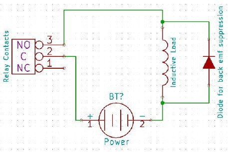
Using Relay Modules with Inductive Loads
It is important to take additional care when using relays with inductive loads. An inductive load is pretty much anything that has a coil and works based on magnetic principles like Motors, Solenoids and transformers. Inductive loads produce back emf when the magnitude of the load current changes. The back emf can be in the order of tens or even hundreds of voltage (See this Wikipedia article http://en.wikipedia.org/wiki/Counter-electromotive_force). This effect is most severe when power is disconnected from inductive load because the rate of change of current is maximum at that point. Even though the back emf lives only for a very short time (a few milliseconds) it can cause sparks between the relay contacts and can deteriorate the contact quality over time and reduce the life span for the relays considerably.
So it is important to take countermeasures to suppress the back emf to acceptable levels to protect relay contacts. Usually this requires connecting electronic devices in parallel with the load such that they absorb the high voltage components generated by the load. For solenoids, connecting a diode (fast switching diode is recommended) in
parallel to the load (in reverse direction to the load current) is very effective. A diode used for this purpose is usually called a freewheeling diode. Please see the diagram on the right for connection details.
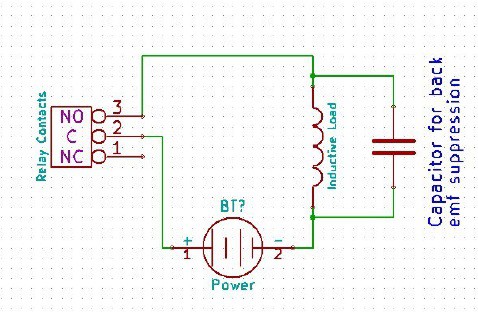
A capacitor with proper rating is recommended for protecting the relay contacts when a motor is used as load. The capacitor should be rated enough to withstand the back emf that is generated by the motor. Please see the diagram below for connection details.
Please note that the relay modules are NOT shipped with back emf suppression devices pre-installed. The exact kind of suppression device and the parameters of the selected device can vary depending on the load itself. Some of the parameters that affects the suppression device selection are the inductance of the load, power supply voltage, load current, physical size/structure of the load etc.. It is obvious that it is impossible for us to predict these parameters and design required back emf suppression device and incorporate that on the board. So we believe this is a task best left to the module user. There is an excellent article on designing back emf suppression on Wikipedia at http://en.wikipedia.org/wiki/Flyback_diode
Technical Specifications
| Parameter * | Value | Unit |
|---|---|---|
| Basic Specifications | ||
| Number of Relays | 16 | |
| Number of GPIO's | 8 | |
| Number of analog inputs (Multiplexed with GPIO's) | 8 | |
| Digital circuit power supply voltage (external) | 12 | V |
| Maximum current drawn by digital circuitry | 600 | mA |
| Relay Specifications | ||
| Nominal relay coil voltage | 12 | V |
| Nominal coil power consumption (per relay) | 360 | mW |
| Relay contact material | Silver Alloy | |
| Contact rating | 1C: 7A 240VAC/ 10A 120VAC | |
| Maximum switching voltage | 250VAC/ 30VDC | |
| Maximum switching current | 10 | A |
| Maximum switching power | 2770VA/ 240W | |
| Contact resistance (initial) | 100 Min at 6VDC 1A | mΩ |
| Life expectancy (Electrical) | 100,000 | Operations |
| Life expectancy (Mechanical) | 10,000,000 | Operations |
| Nominal insulation resistance | 100 Min at 500VDC | MΩ |
| Maximum switching on response time | 10 | mS |
| Maximum switching off response time | 5 | mS |
| IO Specifications | ||
| Maximum IO source current | IO0 – IO9 | 25mA |
| Maximum IO sink current | IO0 – IO9 | 25mA |
| GPIO input low voltage | 0.15 | V |
| GPIO input high voltage | 3.3 | V |
| GPIO output low voltage | 0 | V |
| GPIO output high voltage | 3.3 | V |
| ADC Specifications | ||
| Resolution | 10 | bits |
| Full scale | range 0 – VDD | V |
| Reference voltage | VDD | V |
| Recommended Impedance of Analog Voltage Source | 2.5 | KΩ |
Frequently Ask Questions
Q. What is the connector marked as ICSP on this module?
A. This connector is used to program the on-board microcontroller. This connector is primarily intended for factory use.
Q. I need a customized version of this product, can Numato do the customization for me?
A. Yes, we can definitely do customization but there may be minimum order requirements depending on the level of customization required. Please write to sales@numato.com for a quote.
Q. Where can I buy this product?
A. All Numato products can be ordered directly from our web store http://www.numato.com. We accept major credit cards and Paypal and ship to almost all countries with a few exceptions. We do have distributors in many countries where you can place your order. Please find the current list of distributors at http://numato.com/distrib.
Mechanical Dimensions