Introduction
The most exciting thing about FPGAs is its ability to process problems in a parallel manner. This gives FPGAs clear advantage over microprocessors. But when it comes to implementing sequential algorithms, FPGAs may not be the best option due to increased complexity. The “best of both worlds” option would be to implement sequential algorithms on a microprocessor and custom logic that requires parallelism on FPGA fabric. There are three ways to accomplish this.
- Include a Microprocessor/Microcontroller and FPGA on your board and establish a mechanism for communication between these two elements
- Use an FPGA with a built-in embedded processor such as ARM/PPC
- Build a soft processor within FPGA fabric
All these options have their own advantages and disadvantages. Option 1 will give you a lot of flexibility in terms of what processor and FPGA you want to select. Depending on your application, you could select an 8-bit microcontroller or a 32-bit application processor for sequential logic and choose a low-end CPLD or high-end FPGA for accelerated/parallel logic. It gives a lot of opportunities to optimize cost as well. But the disadvantages would be taking up extra space on the board, need to implement a custom communication mechanism for interaction between these two elements, two separate toolsets, and workflows for microprocessor and FPGA.
Option 2 would be best suited for applications where there is a heavy requirement of both sequential and parallel/accelerated logic. Many leading manufacturers offer FPGA devices with built in ARM or PPC embedded processors. Usually, these are high-end devices with powerful embedded processors and a lot of FPGA logic resources. The advantages of this option would be lower PCB real estate since both FPGA fabric and the embedded processor are in the same package, Single toolset, and integrated workflow, Well established communication options between FPGA fabric and embedded processor and usually vendor tools are aware of these options which make using these in the design very easy. Since the processors are not built on FPGA fabric, they can run at higher speeds. The single biggest disadvantage of this option would be the cost. Since these devices are usually found in high-end offerings of their product line, the cost may not be justifiable unless your design really needs such processing power.
Option 3 sits somewhat in the middle in terms of advantages and disadvantages. Building a soft processor on FPGA fabric has some clear advantages. A soft processor can be implemented on a low, mid or high-end FPGAs depending on your application (less cost). The soft processor saves PCB real estate since it is fully contained within FPGA. Since they are implemented on FPGA logic, they are highly customizable (compared to option 2 where processor features are not customizable). The one biggest disadvantage of soft processors is that they eat up a lot of resources on the FPGA so you will have fewer logic resources and BRAM to use for your custom peripherals and logic. Another disadvantage is that the soft processors can run only at lower clock speeds compared to hard processors in option 2.
In this article, we will take a closer look at option 3 since that is the best option for Xilinx Spartan 6 series devices (and thus for Saturn V3 Spartan 6 FPGA Development Board).
Tools and Prerequisites
- A Saturn V3 Spartan 6 FPGA Development Board (LX45 variant used in this article)
- Xilinx EDK (Available from http://www.xilinx.com. Download and install Xilinx ISE Webpack (not VIVADO) with EDK. You can obtain the ISE Webpack license and EDK license from http://www.xilinx.com.
- A Xilinx Platform USB JTAG cable (Optional, we will discuss how to get the sample design running without this cable. This is very useful though if you are planning to do any serious development since Chipscope and source level debugging can only be done with a Platform USB cable. There are some cheap options available here. Please don’t quote us on this, we can’t vouch for their quality)
- Saturn Configuration Downloader app. Can be downloaded from Saturn V3 product page
- FT_Prog tool for configuring onboard FT2232H USB Serial converter(download and install from here)
This article expects you to have reasonable experience handling development boards and understanding basic FPGA and programming concepts.
What is Microblaze?
Microblaze is a 32-bit soft processor IP that is developed by Xilinx for their mid to high-end FPGA devices. Microblaze is compatible with their Spartan 6, Virtex and Zynq devices. You can find more resources including the datasheet for Microblaze at Xilinx’s Microblaze page. Fortunately, we do not need to download Microblaze IP separate since it is bundled with the Xilinx EDK tool. Microblaze based embedded design can use either PLB or AXI as the bus system. Since Xilinx is planning to phase out PLB and keep only AXI in the future, we will stick With AXI for our designs. You do not need deep knowledge of Microblaze or AXI to follow this article and build a working system successfully.
What is AXI?
AXI stands for Advanced eXtensible Interface. AXI is a bus interconnect based on ARM’s popular AMBA bus architecture. In a Microblaze system, AXI connects the microprocessor to all peripherals in the system. The only exception is Block RAM which is attached to the processor through LMB (Local Memory Bus). AXILite is available for connecting low throughput peripherals to the system such as UART, GPIO, etc… AXILite uses fewer logic resources on FPGA compared to AXI. Usually, AXI is used to connect high throughput peripherals such as DDR memory, Ethernet, etc. Again, a detailed understanding of AXI is not required for following this article. But for the curious readers, AXI Reference Guide is available here.
What is EDK?
EDK is a set of development tools provided by Xilinx to help create a Microblaze based embedded system and develop software for the system. Xilinx EDK has two main components.
- Xilinx Platform Studio (XPS)
- Xilinx Software Development Kit (SDK)
These are the two separate software tools that we will use to design and implement our system. XPS is the tool used for designing and generating the hardware system. You will create and configure the Microblaze processor and necessary peripherals using XPS and generate a bit file from the design. This bit file will be programmed to the FPGA to complete the hardware design. SDK is the tool where the software is written for the Microblaze processor. The software can be written using C or C++. SDK and XPS together will generate all necessary header files and linker scripts needed to successfully build the software for your system. We will take a detailed look at these tools as we go forward. More details about these tools can be found here.
Tool Version Compatibility and Help
This article uses Xilinx EDK shipped with Xilinx ISE 14.6. So the screenshots and directions/commands may be different on your system if you are using a different version. Please adapt the steps mentioned in this article to make it work with your specific tool version. The best place to ask questions about ISE, EDK (XPS/SDK), Microblaze and Spartan 6 FPGA is Xilinx community forums at http://forums.xilinx.com/. You may optionally open a web case at http://www.xilinx.com/support/clearexpress/websupport.htm. Questions specific to Saturn Spartan 6 FPGA Development Board may be asked at the comments section on the product page or contact Numato Lab.
Creating Microblaze Based Embedded Hardware Platform
In this section, we will see how to create a basic Embedded Platform based on Microblaze using Xilinx Platform Studio (XPS). We will use the base System Builder (BSB) wizard to generate the system. To use BSB to generate a system for Saturn, you will need to download the supporting files from here and extract to the folder “C:\Xilinx\xx.xx\ISE_DS\EDK\board”. Once extracted, the complete path to the file should look like “C:\Xilinx\xx.xx\ISE_DS\EDK\board\NumatoLab\ipxact\Saturn_LX45_V3\data”. Once files extracted properly, go to All Programs > Xilinx Design Tools > EDK and click on Xilinx Platform Studio icon. Once XPS is loaded, click on “New BSB Project” under File menu or press Ctrl + Shift + B to invoke the BSB wizard. If everything went fine, the BSB wizard window will pop up as shown below.
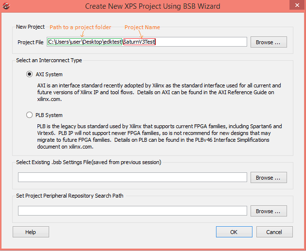
Enter the path to a folder where you want to store the project and a project name. Select the AXI System in the interconnect Type section and click OK. In the next page of the wizard, select “Numato Lab” from the board Vendor combo box (This option should be available if you have placed the BSB wizard support files for Saturn properly as mentioned earlier). Select Saturn LX45 and 3.0 from Board Name and Board version combo boxes respectively and click the “Next” button.
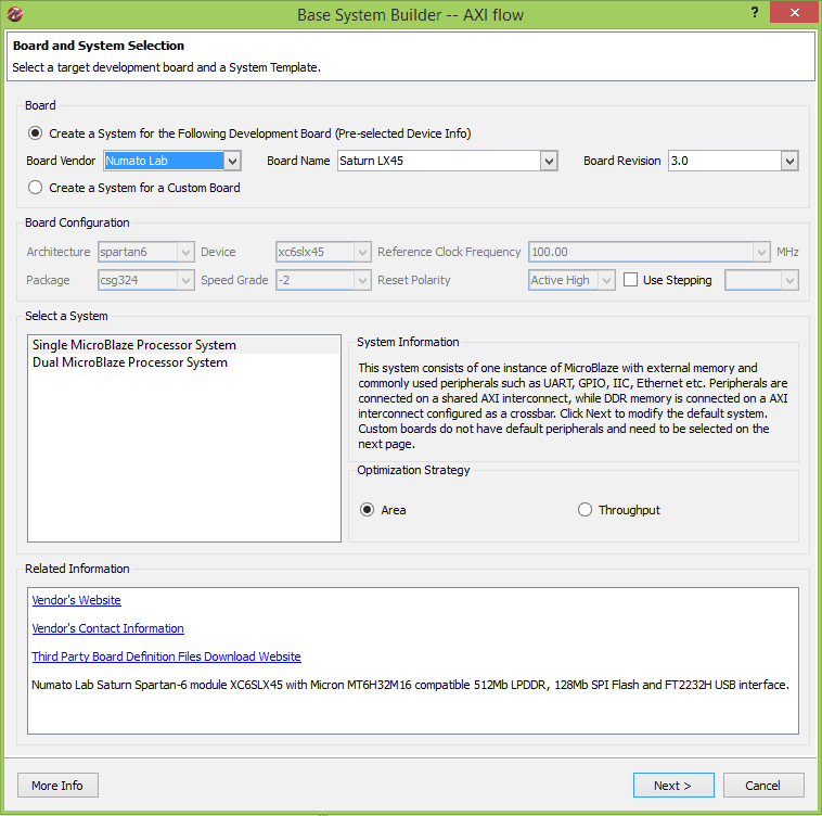
You can set the Optimization strategy to Area or Throughput. We will leave it at the default option “Area” for this example. Click Next to proceed to the next page of the wizard. In the next page, you will have an option to select peripherals as shown in the image below.
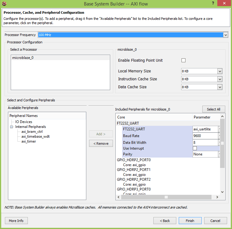
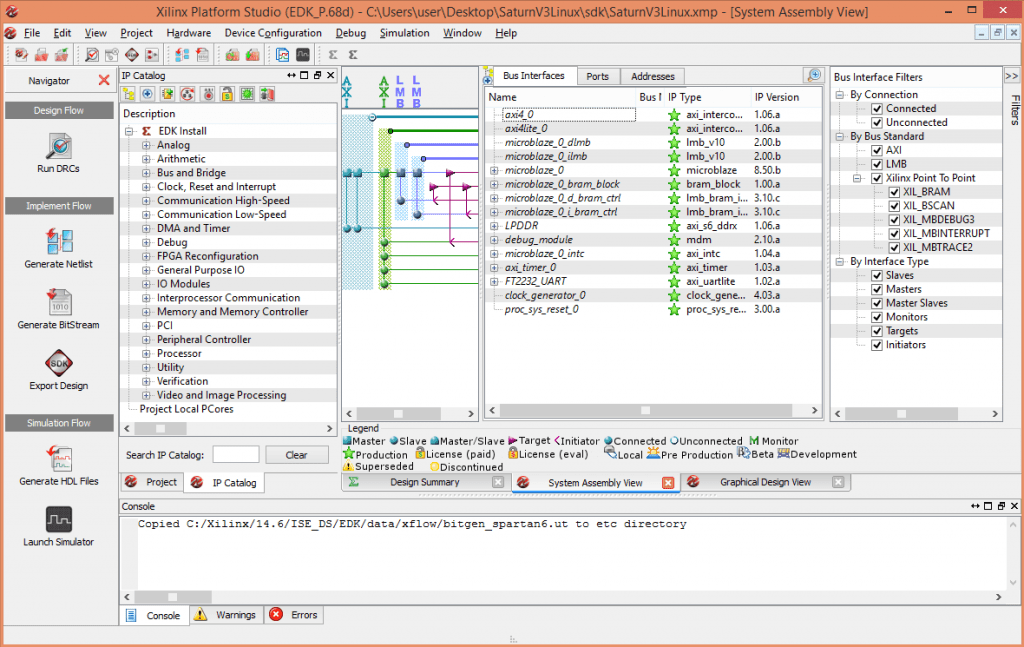
Leave everything in this page to its defaults and click Finish. At this point, XPS will generate the system for you and you will be presented with a window like below.
This window shows all IPs available, IPs used in the design and bus connections between the IPs used. Here you may notice that DDR memory is connected to the Microblaze processor through AXI bus since DDR requires better throughput. But all other peripherals are connected to AXI Lite. Surprisingly this system is fully functional as is without any customization or modifications. So for the sake of simplicity, we will leave everything as it is and continue to build the system. Click on the “Generate Bitstream” button on the left to compile the system and build the bitstream. This step may take a few minutes to a few tens of minutes depending on the speed of your computer.
Once the bit file is generated successfully, click on the “Export Design” button on the toolbar on the left. Click on the “Export Only” button on the window that pops up. This step will export all necessary files for creating an SDK project into a convenient directory (usually inside SDK\SDK_Export\hw under the current project directory). At this point, we have the hardware system ready. This is more or less equivalent to having a microprocessor/microcontroller board without and code written for it. So our next step is to write some code and build it.
Creating an Application program for Microblaze based Embedded Platform
We will use the Xilinx SDK to write and compile code for the hardware platform we just built. Xilinx SDK is an Eclipse-based tool that can create, build, debug and maintain projects for Xilinx Microblaze based platforms (well it supports non-microblaze based embedded platforms as well!). To start SDK, go to All Programs > Xilinx Design Tools > EDK and select “Xilinx Software Development Kit”. When asked to choose a workspace, enter a convenient directory where you would like the projects files to be stored. To create a new SDK project, select “New Application Project” from File menu. You will be presented with a window like shown below.
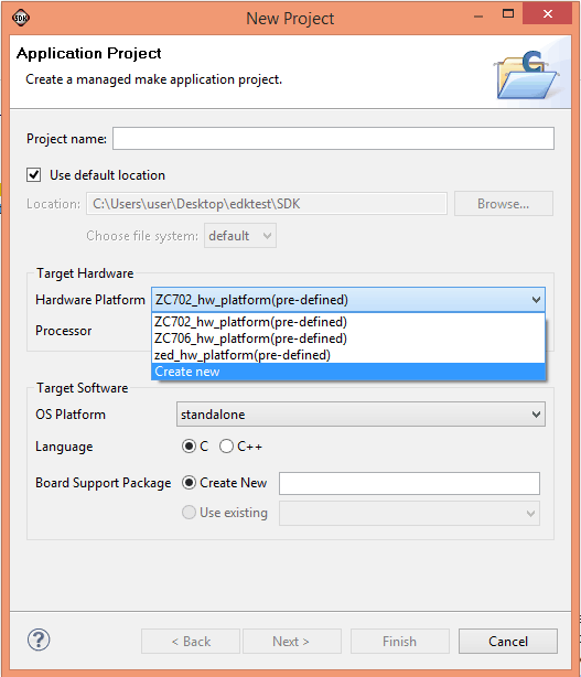
Select create new from the Hardware Platform combo box. A new window will appear where we need to create a new Hardware Project.
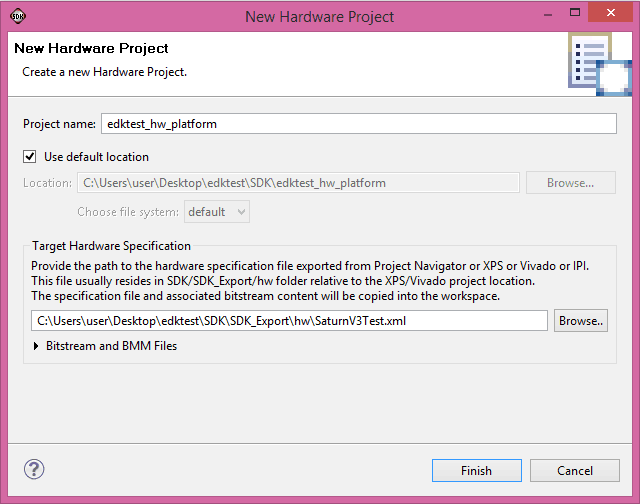
Click on the Browse button and browse to the directory where the XPS project was saved earlier. And browse to SDK\SDK_Export\hw and select SaturnV3Test.xml. This wizard will automatically populate a project name, we will leave it unchanged. Click the “Finish” button to go back to the Application Project Wizard. Back in the application project wizard, enter a project name and leave all other settings to defaults as shown in the image below.
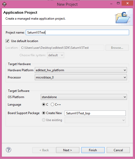
Click next to go to the last page in the application project Wizard. Select “Memory Test” template from the list of templates and click Finish. SDK will create a workspace and add three projects to it. All projects can be viewed in Eclipse Project Explorer as below.
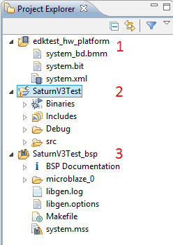 In the image towards the right, you can see three projects. The project marked as number 1 is the hardware platform. These files are copied directly from the directory where XPS exported the hardware system to. Number 2 is the application project that we will be working on. Number 3 is the BSP project which was automatically generated by SDK. The libraries and include files necessary for our application to work are stored under this project.
To build the project, select “Build All” from the Project menu. If everything went fine so far, the project should build with no errors. Again this is a working project which can be downloaded and tested on hardware without any modifications. If you would like to see the code, go to src folder under SaturnV3Test project and open the source files listed there. memorytest.c has the main() function.
Testing the System
We have generated a hardware platform using XPS and created necessary software using SDK. Now it is time to program this on to the real hardware and test the functionality. Before we can do this, we have to prepare the Saturn Spartan 6 FPGA Development Board. All that we need to do is to configure channel B of the FT2232H on Saturn as a serial port so that we can see the data printed from our EDK application using a serial terminal program. Configuring FT2232H on Saturn is covered in a separate article here. Please follow the steps in the article and configure the board accordingly. Now Saturn’s Channel B should be visible in device manager as a Serial port. Use your favorite serial terminal utility (Hyperterminal, Tera Term, PUTTY etc..) and open the serial port corresponds to Saturn’s FT2232H Channel B. Set the baud rate to 9600, no parity and no flow control (You may have noticed we left the default FT2232H UART settings unchanged when we created the hardware platform. The default baud rate selected by XPS is 9600). Leave the serial port open so we can see messages as soon as they are printed.
At this point, we have two options to download the design to Saturn and test. The first option is to use a Xilinx Platform cable USB and download the design to the board and run. If you don’t have a Xilinx Platform USB cable handy, you can generate a binary file from the design and download to the board using Saturn Configuration tool.
Option 1 – Using Xilinx Platform cable USB
Assuming you have already connected your Platform Cable USB to Saturn and the host PC properly (If not, please set it up). To download the bit file (for Microblaze system) and test application binary (usually .elf file), go to “Xilinx Tools menu and select “Program FPGA”.
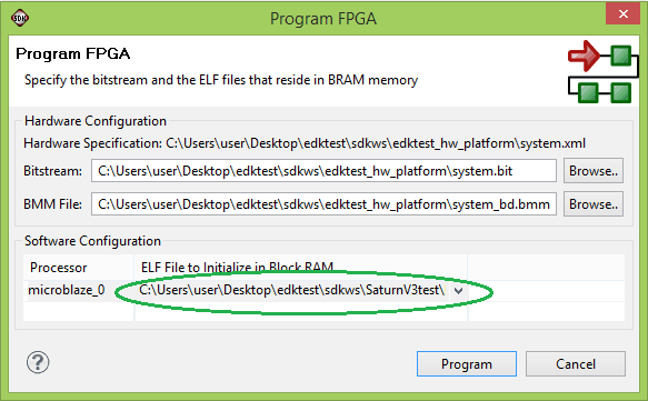
In the window that pops up, select the .elf file (which is the executable generated by SDK) instead of boot loop (please image above). Click the “Program” button to complete configuring FPGA and loading the elf file. For bigger programs that do not fit inside FPGA Block RAM, you will need to select boot loop instead.
Now it is time to run the program. Before starting the program, go ahead and launch your favorite serial terminal program and open the serial port corresponding to Saturn. Set baud rate to 9600 and handshaking to None.
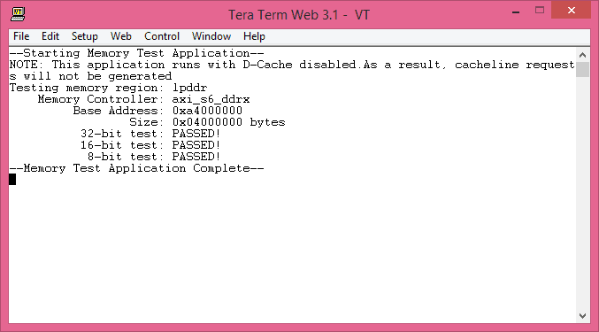
In the SDK project explorer, select “SaturnV3test” project and go to “Run” menu and select “Run”. If asked, select “Launch on hardware (GDB)” and continue. If everything so far went well, you will see memory test status will be printed on the serial terminal as in the image below.
Option 2 – Generate a bin file and download to SPI flash using Saturn Configuration Utility
If you don’t have a Xilinx Platform Cable you can use freely downloadable Saturn Configuration Utility (available for download from Saturn product page) instead of buying one. For those who want to take that route, here are the steps to follow.
The idea is to use Xilinx data2mem tool to merge the FPGA bit file generated by XPS for Microblaze system and the executable generated by SDK. But before we can do that, we will need to change the startup clock settings in the XPS project rebuild (you may do this step right before generating bit file to avoid building the XPS project two times).
By default, XPS will set JTAG clock as FPGA startup clock. This is perfectly fine when we are using a JTAG adapter such as Xilinx Platform Cable – USB for programming FPGA. But to load FPGA configuration from SPI flash, we need to set startup clock to Cclk instead of JTAGCLK. To do this, go to the “Project” tab right next to the “IP Catalog” tab in XPS and open the Bitgen Options file “etc/bitgen.ut”. Change the line “-g StartUpClk:JTAGCLK” to “-g StartUpClk:CCLK”. Save the file and rebuild the project by clicking the “Generate bit file ” button on the left pane. Once bit file is generated with the changes, you may want to export the design by clicking the “Export Design” button and rebuild the SDK project.
Please note that the above step (changing startup clock) is very important. Don’t skip it otherwise, the FPGA will not start.
Once all changes are done and rebuilding is finished, we need to find the following files.
- The bit file (The file name should be SaturnV3Test.bit if you used the same project name as mine. This file is located in the folder SDK\SDK_Export\hw inside the XPS project folder)
- The executable file (The file name should be SaturnV3test.elf if you used the same project name as mine. This file is located in the folder SaturnV3test\Debug inside the SDK workspace folder)
- The .bmm file (The file name should be SaturnV3Test_bd.bmm if you used the same project name as mine. This file is located in the folder SDK\SDK_Export\hw inside the XPS project folder)
Once all these three files are copied to a common folder, open command line prompt and move to that folder. Follow the two steps below to generate the final bin file.
Step 1
cmd>c:\Xilinx\xx.x\ISE_DS\settings64.bat
cmd>data2mem -bm SaturnV3Test_bd.bmm -bd SaturnV3test.elf -bt SaturnV3Test.bit
Make sure to replace xx.x in the first command with your ISE version to form a correct path and use correct file names in the second command (if your XPS/SDK project names were different). If the commands did run successfully, you should see a new bit file generated in the folder (SaturnV3Test_rp.bit in my case).
Step 2
Now we need to generate a bin file. Run the following command in the same command window.
cmd>promgen -w -p bin -u 0x0 SaturnV3Test_rp.bit -spi -o download_me
If the command was successful, you see a few new files generated in the folder. One of the files will be download_me.bin. We will use this file to configure the Saturn Spartan 6 FPGA module. Run Saturn flash configuration tool, select download_me.bin and click the “program” button as in the image below.
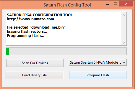
Keep the Serial terminal program running, while configuration progress. Once the configuration is completed, the FPGA will boot from SPI flash and will run the memory test application. You will see the memory test results printed at the serial terminal as below.

Conclusion
Though implementing a processor-based embedded system on an FPGA is a fairly complex process, simple and powerful tools such as XPS and EDK make it an easy task. Xilinx EDK provides graphical tools to design and generate complex systems fast and easy.
I followed the steps to download the BSB support code and the file path is correct, however Numato is not an option from board vendor. Am I doing something wrong? How can this be fixed?
June 28, 2017 at 7:52 pmGood Morning Sir,
I want to thank you for this very helpful tutorial , it was a little bit hard, but i manage to make it work, may i ask if the Spartan 3E development kit is available in the XPS .
Have a good day sir.
December 7, 2018 at 8:15 pm